33
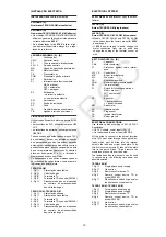
BURNER OPERATION
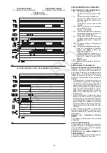
BURNER STARTING (A)
• 0s:
Load control TL closes.
Fan motor starts.
• 6s:
Servomotor starts:
90° rotation to right, until contact is
made on cam I (E)p.24.
The air gate valve is positioned to
MAX. output.
• 30s:
Pre-purge stage with air delivery at
MAX. output.
Duration 31 seconds.
• 61s:
Servomotor rotates to left up to the
angle set on cam I I I (E)p.24 for MIN.
output.
• 81s:
The air gate valve and the gas butter-
fly are positioned to MIN. output with
cam I I I(E)p.24 at 15°.
• 84s:
Ignition electrode strikes a spark.
• 90s:
Safety valve VS and adjustment valve
VR (rapid opening) open. The flame is
ignited at a low output level, point A.
Delivery is then progressively
increased, with the valve VR opening
slowly up to MIN. output, point B.
• 93s:
The spark goes out.
• 114s: The control box starting cycle ends.
STEADY STATE OPERATION (A)
Burner without outputregulator RWF40
At the end of the starting cycle, the servomotor
control then passes to the load control TR for
boiler pressure or temperature, point C.
(The LFL control box continues, however, to
check that the flame is present and that the air
and gas max. pressure switches are in the cor-
rect position.)
• If the temperature or pressure is low (and the
TR load control is consequently closed), the
burner progressively increases its output to
the MAX. value, (section C-D).
• If subsequently the temperature or pressure
increases until TR opens, the burner progres-
sively decreases its output to the MIN. value
(section E-F).
And so on.
• The burner locks out when demand for heat is
less than the heat supplied by the burner at
min. output, (section G-H).
Load control TL opens. The servomotor
returns to the 0° angle limited by contact with
cam I I (E)p.24. The gate valve closes com-
pletely to reduce thermal dispersion to a mini-
mum.
Every time output is changed, the servomotor
automatically modifies gas delivery (gas butter-
fly valve) and air delivery (fan gate valve).
Burner with output regulator RWF40
See the handbook enclosed with the regulator.
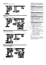
FIRING FAILURE (B)
If the burner does not fire, it goes into lock-out
within 3 s of the opening of the gas solenoid
valve and 93 s after the closing of control device
TL.
The control box pilot light will light up.
BURNER FLAME GOES OUT DURING OPER-
ATION
If the flame should accidentally go out during
operation, the burner will lock out within 1s.
FUNCIONAMENTO DO QUEIMADOR
ARRANQUE DO QUEIMADOR (A)
• 0s:
Fecha-se o termostato TL.
Entra em funcionamento o motor ven-
tilador.
• 6s:
Entra em funcionamento o servomo-
tor:
roda para a direita 90°, isto é, até que
intervém o contacto da leva I (E)p. 24.
O registo do ar coloca-se na MÁX
potência.
• 30s:
Fase de pré-varrimento, com o caudal
dear à MÁX potência.
Duração: 31 segundos.
• 61s:
O servomotor roda para a esquerda,
até ao ângulo regulado na leva I I I
(E)p.24 para a MÍN potência.
• 81s:
O registo do ar e a válvula de borbo-
leta do gás colocam-se na MÍN potên-
cia; com a leva I I I)(E)p.24 a 15°.
• 84s:
Gera-se faísca no eléctrodo de acen-
dimento.
• 90s:
Abrem-se as electroválvulas de segu-
rança VS e de regulação VR (abertura
rápida). Acende-se a chama, com
pouca potência, ponto A.
Continua um progressivo aumento da
potência, abertura lenta da electrovál-
vula VR, até à potência MÍN, ponto B.
• 93s:
A faísca apaga-se.
• 114s: Finaliza o ciclo de arranque da caixa
de controlo.
FUNCIONAMENTO A REGIME (A)
Queimador sem Regulador de Potência
RWF40
Finalizado o ciclo de arranque, o comando do
servomotor passa ao termostato TR, que con-
trola a pressão ou a temperatura da caldeira,
ponto C. (A caixa de controlo continua a contro-
lar a presença de chama e a correcta posição
dos pressostatos de ar e de gás de máxima).
• Se a temperatura ou a pressão for baixa e
consequentemente o termostato TR estiver
fechado, o queimador aumenta progressiva-
mente a potência até ao valor MÁX (seg-
mento C-D).
• Se seguidamente a temperatura ou a pressão
aumentam até à abertura do termostato TR, o
queimador reduz progressivamente a potên-
cia até ao valor MÍN (segmento E-F). E assim
sucessivamente.
• A paragem do queimador faz-se quando a
procura de calor é inferior à gerada pelo quei-
mador à potência MÍN (segmento G-H). O
termostato TL abre-se, o servomotor
regressa ao ângulo 0º, limitado pelo contacto
da leva II (E)p.24. O registo fecha-se comple-
tamente para reduzir as perdas de calor ao
mínimo.
A cada alteração de potência, o servomotor
altera automaticamente o caudal de gás (vál-
vula de borboleta) e o caudal de ar (registo ven-
tilador).
Queimador com Regulador de Potência
RWF40
Ver o Manual de Instruções que acompanha o
Regulador.
FALTA DE ACENDIMENTO (B)
Se o queimador não se acende, produz-se o
bloqueio do mesmo ao fim de 3 segundos da
abertura da válvula de gás e aos 93 segundos
do fecho do termostato TL.
EXTINÇÃO DA CHAMA DURANTE O FUNCI-
ONAMENTO
Se a chama se apagar durante o funciona-
mento, o queimador bloqueia-se em 1 segundo.
ATC
ROC
Summary of Contents for TECNO 28-GM
Page 39: ...A T C R O C...

