background image

38

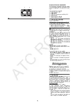
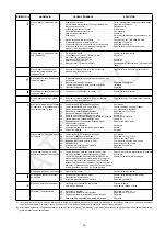
(1) The control box 22)(A)p.6 is fitted with a disc  which rotates during the firing programme, which can be seen through the transparent lock-out reset button. When

the burner does not fire or comes to halt following a fault, the symbol which appears behind the reset button indicates the type of problem.

(2) The fuse is located in the rear part of the control box 22)(A)p.6. A pull-out fuse is also available as a spare part which can be fitted after breaking the tag on the

panel which holds it in place.

SYMBOL 

(1)

FAULT

PROBABLE CAUSE

SUGGESTED REMEDY

The burner does not start

1

- No electrical power supply  . . . . . . . . . . . . . . . . . . . . . . . . . Close all switches - Check connections

2

- A limiter or safety control device is open . . . . . . . . . . . . . . . Adjust or replace

3

- Control box lock-out  . . . . . . . . . . . . . . . . . . . . . . . . . . . . . . Reset control box

4

- Control box fuses blown  . . . . . . . . . . . . . . . . . . . . . . . . . . . Replace 

(2)

5

- Erroneous electrical connections  . . . . . . . . . . . . . . . . . . . . Check connections

6

- Defective control box . . . . . . . . . . . . . . . . . . . . . . . . . . . . . . Replace

7

- No gas supply . . . . . . . . . . . . . . . . . . . . . . . . . . . . . . . . . . . Open the manual valves between meter and 

train

8

- Mains gas pressure insufficient . . . . . . . . . . . . . . . . . . . . . . Contact your GAS COMPANY

9

- Minimum gas pressure switch fails to close  . . . . . . . . . . . . Adjust or replace

10 - Air pressure switch in operating position   . . . . . . . . . . . . . . Adjust or replace
11 - Cam I I servomotor contact does not operate . . . . . . . . . . . Adjust cam I I or replace servomotor

control box terminals 11-8

The burner does not start 
and a function lock out occurs

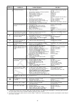
12 - Flame simulation   . . . . . . . . . . . . . . . . . . . . . . . . . . . . . . . . Replace control box
13 - Defective capacitor (TECNO 28-GM)
14 - Defective motor remote control switch (TECNO 38/50-GM) Replace
15 - Defective electrical motor  . . . . . . . . . . . . . . . . . . . . . . . . . . Replace
16 - Motor protection tripped (TECNO 38/50-GM) . . . . . . . . . . . Reset thermal cut-out when third phase is re-

connected

The burner starts 
but stops at maximum 
gate valve setting

17 - Cam I servomotor contact does not operate . . . . . . . . . . . . Adjust cam I or replace servomotor

control box terminals 9-8

The burner starts 
and then locks out

Air pressure switch inoperative due to
insufficient air pressure:

18 - Air pressure switch adjusted badly . . . . . . . . . . . . . . . . . . . Adjust or replace
19 - Pressure switch pressure point pipe blocked  . . . . . . . . . . . Clean
20 - Head wrongly adjusted . . . . . . . . . . . . . . . . . . . . . . . . . . . . Adjust

The burner starts and 
then locks out

21 - Fault in flame detection circuit . . . . . . . . . . . . . . . . . . . . . . . Replace control box

The burner stays 
in the pre-purge stage

22 - Cam I I I servomotor contact does not operate . . . . . . . . . . Adjust cam I I I or replace servomotor

control box terminals 10-8

After pre-purge and 
safety time, 
the burner goes to lock-out 
and the flame does not appear

23 - The solenoid VR allows little gas through . . . . . . . . . . . . . . Increase
24 - Solenoid valves VR or VS fail to open . . . . . . . . . . . . . . . . . Renew the coil or rectifier panel
25 - Gas pressure too low  . . . . . . . . . . . . . . . . . . . . . . . . . . . . . Increase pressure at governor
26 - Ignition electrode wrongly adjusted . . . . . . . . . . . . . . . . . . . Adjust, see fig. (C)p.12
27 - Electrode grounded due to broken insulation . . . . . . . . . . . Replace
28 - High voltage cable defective . . . . . . . . . . . . . . . . . . . . . . . . Replace
29 - High voltage cable deformed by high temperature . . . . . . . Replace and protect
30 - Ignition transformer defective  . . . . . . . . . . . . . . . . . . . . . . . Replace
31 - Erroneous valve or transformer electrical connections . . . . Repeat connection
32 - Control box defective. . . . . . . . . . . . . . . . . . . . . . . . . . . . . . Replace
33 - A cock down-line of the gas train is closed . . . . . . . . . . . . . Open
34 - Air in pipework. . . . . . . . . . . . . . . . . . . . . . . . . . . . . . . . . . .  Bleed air

The burner goes to lock-out 
right after flame appearance

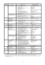
35 - The solenoid VR allows little gas through . . . . . . . . . . . . . . Increase
36 - Ionisation probe wrongly adjusted. . . . . . . . . . . . . . . . . . . . Adjust, see fig. (C)p.12
37 - Faulty electrical connections for probe  . . . . . . . . . . . . . . . . Repeat connection
38 - Insufficient ionisation (less than 6 µA). . . . . . . . . . . . . . . . . Check probe position
39 - Probe grounded. . . . . . . . . . . . . . . . . . . . . . . . . . . . . . . . . . Withdraw or replace cable
40 - Max. gas pressure switch operates . . . . . . . . . . . . . . . . . . . Adjust or replace
41 - Defective control box . . . . . . . . . . . . . . . . . . . . . . . . . . . . . . Replace

The burner repeats 
the starting cycle 
without lock out

42 - Mains gas pressure is near the value to which the . . . . . . . Reduce operating pressure

min. gas pressure switch gas is adjusted. The

of minimum gas pressure

repeated drop in pressure which follows valve

switch.

opening causes temporary opening of the pressure

Replace gas filter.

switch itself, the valve immediately closes and the
burner comes to a halt. Pressure increases again, the
pressure switch closes again and the firing cycle is
repeated. The sequence repeats endlessly.

Lock out without symbol indication 43 - Flame simulation . . . . . . . . . . . . . . . . . . . . . . . . . . . . . . . . . Replace control box

During operation, the 
burner stops in lock out

44 - Probe or ionisation cable grounded  . . . . . . . . . . . . . . . . . . Replace worn parts
45 - Fault on air pressure switch. . . . . . . . . . . . . . . . . . . . . . . . . Replace
46 - Max. gas pressure switch operates . . . . . . . . . . . . . . . . . . . Adjust or replace

Lock out when burner stops

47 - Flame remains in combustion head  . . . . . . . . . . . . . . . . . . Eliminate persistence of flame

or flame simulation  . . . . . . . . . . . . . . . . . . . . . . . . . . . . . . . or replace control box

Ignition with pulsation

48 - Poorly adjusted head. . . . . . . . . . . . . . . . . . . . . . . . . . . . . . Adjust, see page 15
49 - Ignition electrode wrongly adjusted . . . . . . . . . . . . . . . . . . . Adjust, see fig. (C),page 12
50 - Poorly adjusted fan air gate: too much air . . . . . . . . . . . . . . Adjust
51 - Output during ignition phase is too high  . . . . . . . . . . . . . . . Reduce

P

1

ATC 

ROC

Summary of Contents for TECNO 28-GM

Page 1: ...e Instalaci n Funcionamiento y Mantenimiento Queimadores a g s Funcionamento a duas chamas progressivas ou modulante Instru es de Instala o Funcionamento e Manuten o Blown type gas burners Progressive...

Page 2: ...do queimador 25 Acendimento do queimador 25 Regula o do queimador 27 1 Pot ncia de acendimento 27 2 Pot ncia M X 27 3 Pot ncia M N 29 4 Pot ncias interm dias 29 5 Pressostato de ar 31 6 Pressostato g...

Page 3: ...32 38 44 51 58 68 Presi n al m ximo caudal 2 mbar 7 5 11 1 6 6 9 7 7 2 10 6 FUNCIONAMIENTO Intermitente m n 1 paro en 24 horas Estos quemadores tambi n son apropiados para servicio continuo si est n e...

Page 4: ...44 51 58 68 Press o a m ximo caudal 2 mbar 7 5 11 1 6 6 9 7 7 2 10 6 FUNCIONAMENTO Intermitente m n 1 paragem em 24 horas Estes queimadores tamb m s o apropriados para o servi o cont nuo se estiverem...

Page 5: ...ure at max delivery 2 mbar 7 5 11 1 6 6 9 7 7 2 10 6 OPERATION On Off 1 stop min each 24 hours This burner is also fitted for the continuos operation if it is equipped with the control box LANDIS type...

Page 6: ...del Regulador de poten cia RWF40 27 Conector cable sonda de ionizaci n Hay dos posibilidades de bloqueo del quema dor BLOQUEO CAJA DE CONTROL La iluminaci n del pulsador de la caja 22 A indica que el...

Page 7: ...ar a flange do queimador caldeira 5 Passacabos liga o el ctrica TECNO 28 GM 6 Passacabos liga o el ctrica TECNO 38 50 GM 1 Instru es 1 Lista de pe as de substitui o BURNER DESCRIPTION A 1 Combustion h...

Page 8: ...era de prueba Ejemplo Potencia 350 Mcal h di metro 50 cm longitud 1 5 m CALDERAS COMERCIALES En el acoplamiento quemador caldera no hay ning n problema si la caldera tiene la homologa ci n CE y si las...

Page 9: ...E ou com as dimens es da c mara de combust o muito mais pequenas que as indicadas no gr fico B deve se consultar o fabricante FIRING RATES A During operation burner output varies between a MAXIMUM OUT...

Page 10: ...kW Este valor sirve como primera aproximaci n el real se determinar a trav s del contador En cambio para conocer la presi n de gas necesaria en la toma 1 B una vez fijada la potencia M X a la que se d...

Page 11: ...cia de 210 kW na tabela do TECNO 28 GM coluna 1A 4 mbar Press o na c mara de combust o 2 mbar 4 2 6 mbar press o necess ria na toma 1 B GAS PRESSURE The adjacent tables show minimum pressure losses al...

Page 12: ...como se muestra en la figura C Luego separar el cabezal de combusti n del resto del quemador fig B Desenroscar los tornillos 14 y extraer la envolvente 15 Desenganchar la articulaci n 4 del sector gr...

Page 13: ...poder danificar o amplificador da caixa de con trolo INSTALLATION BOILER PLATE A Drill the combustion chamber locking plate as shown in A The position of the threaded holes can be marked using the th...

Page 14: ...de dicha presi n abrir el disco 2 B hasta la posici n 4 5 Verificar que la combusti n sea satisfactoria y sin pulsaciones B La potencia M N del quemador est com prendida en los valores de la tabla D R...

Page 15: ...e para fora o cabo de alta tens o e da sonda de ioniza o at que estejam ligeiramente esticados SETTING THE COMBUSTION HEAD Installation operations are now at the stage where the blast tube and sleeve...

Page 16: ...ueidad de las electrov lvulas 8 9 Seg n la norma EN 676 el control de estanqueidad es obligatorio para quemadores con poten cia m xima superior a 1200 kW 14 Adaptador rampa de gas quemador 15 Presosta...

Page 17: ...da linha de g s por encomenda Nota Para a regula o da linha de g s ver as ins tru es que acompanham a mesma GAS LINE The gas train must be connected to the gas attachment 1 A using flange 2 gasket 3...

Page 18: ...menos H05 RR F Todos los cables que vayan conectados a la regleta 7 C del quemador deben canalizarse a trav s de los pasacables que se suministran y que deben introducirse por los agujeros corres pond...

Page 19: ...nda RWF40 5 Pg 11 V lvulas de g s 6 Pg 11 Pressostato de g s ou dispositivo de controlo de estanquecidade das v lvulas de g s ELECTRICAL SYSTEM ELECTRICAL SYSTEM as set up by the manu facturer LAYOUT...

Page 20: ...rruptor paro manual quemador MB Regleta de conexiones quemador XP Conector de control de estanqueidad PG Presostato gas de m nima S Se alizaci n de bloqueo a distancia S1 Se aliz bloqueo control estan...

Page 21: ...Electrov lvula de seguran a NOTA Os termostatos TR e TL n o s o necess rios quando se instala o Regulador RWF40 para o funcionamento modulante a sua fun o desempenhada pelo pr prio Regulador LAYOUT A...

Page 22: ...n est igualmente asegurada Nota Los quemadores TECNO 38 50 GM salen de f brica preparados para una alimentaci n el c trica a 400 V Si la alimentaci n es a 230 V cambiar el conexionado del motor de es...

Page 23: ...e os queimadores t m Aten o N o inverter o Neutro com a Fase na linha de alimenta o el ctrica LAYOUT A Connection of RWF40 and related probe to TECNO 28 38 50 GM burners modulating operation Note The...

Page 24: ...las levas est n reguladas del siguiente modo Leva I 90 Limita la rotaci n m xima Con el quemador funcionando a la M X potencia la v lvula de mariposa del gas debe estar completamente abierta 90 Leva...

Page 25: ...se no man metro do tubo em U D Uma vez efectuado o acendimento proceder se regula o completa do queimador ADJUSTMENTS BEFORE FIRST FIRING Adjustment of the combustion head and air and gas deliveries...

Page 26: ...a 300 kW con ts 2 s 200 kW con ts 3 s Para medir la potencia de encendido Desconectar la conector 27 A p 6 del cable de la sonda de ionizaci n el quemador se enciende y se bloquea pasado el tiempo de...

Page 27: ...do g s sa da e se j est no m nimo fechar um pouco a electrov lvula de regula o VR Se for necess rio aument la aumentar a press o de g s sa da do regulador Nm3 h caudal m x queimador 360 BURNER CALIBRA...

Page 28: ...al de la leva 4 A actuando sobre los tornillos de la leva que aparecen en el interior de la abertura 6 A Si es posible no girar el primer tornillo dado que es el que se utiliza para cerrar el registro...

Page 29: ...you notice any sign of pulsations reduce the ignition stage delivery Regula o do ar Variar progressivamente o perfil final da leva 4 A actuando sobre os parafusos da leva que aparecem no interior da...

Page 30: ...TO GAS DE M XIMA B Efectuar la regulaci n del presostato de gas de m xima despu s de haber efectuado todas las dem s regulaciones del quemador con el pre sostato de gas de m xima ajustado al final de...

Page 31: ...de 6 A O queimador gera uma corrente imediatamente superior n o pre cisando normalmente de nenhum controlo No entanto se desejar medir a corrente de ioniza o necess rio desligar a ficha 27 A p 6 do c...

Page 32: ...n de los presostatos de aire y de gas de m xima Si la temperatura o la presi n es baja y en consecuencia el termostato TR est cerrado el quemador aumenta progresivamente la potencia hasta el valor M X...

Page 33: ...er will lock out within 1s FUNCIONAMENTO DO QUEIMADOR ARRANQUE DO QUEIMADOR A 0s Fecha se o termostato TL Entra em funcionamento o motor ven tilador 6s Entra em funcionamento o servomo tor roda para a...

Page 34: ...el registro del aire y la v lvula de mariposa del gas Igualmente los tornillos que fijan los cables el ctricos en la regleta del quemador deben estar bien apretados Limpiar exteriormente el quemador e...

Page 35: ...a enganchar a r tula 3 no sector gra duado 4 FINAL CHECKS with burner running Disconnect one of the wires on the minimum gas pressure switch Open remote control device TL Open remote control device T...

Page 36: ...ja de control Superado el prebarrido y el tiempo de seguridad el quemador se blo quea sin aparecer la llama 23 La electrov lvula VR deja pasar poco gas Aumentarlo 24 La electrov lvula VR o VS no se ab...

Page 37: ...lo Superado o pr varrimento e o tempo de seguran a o queimador bloqueia se sem aparecer a chama 23 A electrov lvula VR deixa passar pouco g s Aument lo 24 A electrov lvula VR ou VS n o se abre Substit...

Page 38: ...servomotor control box terminals 10 8 After pre purge and safety time the burner goes to lock out and the flame does not appear 23 The solenoid VR allows little gas through Increase 24 Solenoid valves...

Page 39: ...A T C R O C...

Reviews: