EN
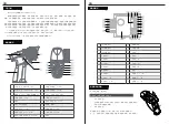
LED Indicator
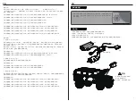
Binding
Stick Calibration
1. R.LED: The red power indicator;
2. G.LED: The green status indicator;
3. Car battery: Two colors light for battery volume display (hereinafter referred to as D3)
•
When the power is high, the D3 green keeps on
•
When the power is medium, the D3 yellow keeps on
•
When the power is low, the D3 red keeps on
When the power is off, the D3 red slow flash
When the receiver drops the code, the tow-colors light is off
•
•
The transmitter and receiver have already been bound at the factory.
This function is used to set the neutral position for throttle and wheel.
Every transmitter is calibrated before leaving the factory, however if recalibration is required,please follow
these steps:
1. Turn and hold the wheel as far clockwise as it will turn, hold the throttle all the way forward, then turn on the
transmitter in calibration mode.
1. Turn on the transmitter while holding the bind button to enter bind mode. G.LED will start flashing quickly.
• Once in bind mode release the bind button.
2. The receiver will power on and wait for 1 second ,if without connection, it will enter the matching code
automatically;
3. Once binding is successful the receiver’s LED will keep on.
Note: When binding, put the transmitter into bind mode first, then the receiver.
The R.LED and G.LED will flash twice.
Car Battery the D3 yellow keeps on
•
•
When calibration is completed the R.LED will be off.
Car Battery the D3 red keeps on
•
•
2. Calibrate wheel: Turn the wheel completely clockwise, then completely counterclockwise.
When calibration is completed the G.LED will be off.
Car Battery the D3 Green keeps on
•
•
3. Trigger calibration: Pull the trigger back then forward as far as it will go.
the two-colors light is of
•
4.Both Wheel and rigger are Calibration passed
5. Once calibration is complete press the bind key to save and exit.
However if the receiver needs to be replaced or additional receivers bound follow these steps:
Note
Power Off
Follow the steps below to turn off the system:
1. Disconnect the receiver power.
2. Toggle the transmitter's power switch to the off position.
Channel Description
Channel Reverse
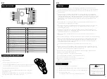
The transmitter outputs a total of 4 channels, which are allocated as follows:
This function is used to adjust the action direction of the servo or motor
The ST.REV / TH.REV switches are the reverse buttons for CH1 and CH2. If the switch is up it indicates reverse, and
the down indicates normal.
Trims
The ST.TRIM is the trims for CH1 (steering ),and can be multiplexed as Trims of CH3 ;
The TH.TRIM is the trims for CH2(throttle).and can be multiplexed as Trims of CH4 ;
For multiplexing switching mode, see [5.5 Mode Switching].
Adjustment range: -120us- + 120us;
ST.TRIM/TH.TRIM: counterclockwise adjustment to increase the trim value. The maximum value is 120 us.
ST.TRIM- / TH.TRIM-: clockwise adjustment to decrease the trim value. The minimum value is -120 us.
D/R
The ST.D/R is the trims for CH1 (steering ),and can be multiplexed as Trims of CH3 ;
The ST.D/R is the trims for CH2(throttle).and can be multiplexed as Trims of CH4 ;
For multiplexing switching mode, see [5.5 Mode Switching].
Adjustment range: 0-120%;
ST.D/R: counterclockwise adjustment to increase the ser vo amount . The maximum value is 120%.
ST.D/R: clockwise adjustment to decrease the ser vo amount . The minimum value is 0%.
TH.D/R: counterclockwise adjustment to increase the servo amount. The maximum value is 120%.
TH.D/R: clockwise adjustment to decrease the servo amount. The minimum value is 0%.
Mode switching
This function is for reusing the ST.TRIM and ST.D / R buttons for different channels
Function setting:
Under normal power-on condition, press the BIND button twice (within 1S) to switch between mode 1 and mode 2.
By default, mode 1 is used.
Mode 1: R.LED is always on. G.LED is off. ST.TRIM is for CH1 trim. ST.D/R is for CH1 ser vo adjustment . TH.TRIM is for
CH2 throttle trim. TH.D/R is for CH2 throttle ser vo adjustment .
Mode 2: R.LED and G.LED are flashing alternately. ST.TRIM is for CH3 trim. ST.D/R is for CH3 ser vo adjustment .
TH.TRIM is for CH4 trim. TH.D/R is for CH4 ser vo adjustment .
Note: By default the output of CH4 is 1000us, after which pressing the button will toggle between 1000 and 2000us.
• CH1:Steering Wheel
• CH2:Throttle Trigger
• CH3:Three-position Switch
• CH4:Key Switch
Make sure to disconnect the receiver power
before turning off the transmitter. Failureto
do so may lead to damage or serious injury.
EN
13
14


