Rockford Systems, LLC
Call: 1-800-922-7533
13
SECTION 2—INSTALLATION
Detect-A-Finger™ Drop Probe Device - Riveter
Mechanical to Electro-Pneumatic Conversion
(continued)
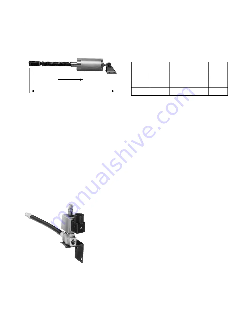
RCL SERIES AIR CYLINDERS
(See Specification Sheet No. KSL-092)
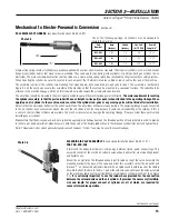
One of the following pull-type air cylinders may be adequate to
operate the machine:
Single-acting spring-return air cylinders are usually supplied with a swivel-clevis mount as standard. Other special cylinders, such as clevis mount,
flange mount (either end) or foot mount are also available. They can be push type (spring inside cylinder), or pull type (spring on cylinder rod, as
illustrated). The main consideration must be that the cylinder is a single-acting spring-return type (not double acting) to meet best safety practices.
When mounting the cylinder, be sure it is secured in such a manner that it will not vibrate loose, bind or rub on some other part of the machine.
The assembly consists of the cylinder, two mounting feet, mounting pin, drive yoke, drive pin, and yoke lock nut. This assembly is illustrated in
Figure 2.3 on the next page. Locate this assembly on the machine so that the feet can be mounted to a convenient surface. The yoke should be
attached to the machine linkage, and the air inlet should be oriented toward the air solenoid valve location.
The air cylinder should be mounted in the most logical position to operate the machine linkage most efficiently.
The main requirement in locating
the cylinder assembly, is that the piston rod will have a straight, in-line pull (or push) when attached to the operating linkage. When
applying an air cylinder to the machine, make sure that the cylinder rod, yoke or any moving parts will not bind after installation.
Adjust so that the air cylinder bottoms at the end of each stroke. The air cylinder will operate in any position. The operating linkage may be connected
to the air cylinder by any convenient means. Be sure the rod stroke is not too long because it could cause jackknifing of the cylinder. If this is
a concern, shorter stroke cylinders are available. Too much air pressure may damage the operating linkage. Please consider these points when
installing any air cylinder.
Make certain that the drive yoke and lock nut are located approximately halfway down on the threaded portion of the piston rod in order to provide
for either up or down adjustment when necessary. Attach one end of the flexible rubber hose in the threaded cylinder inlet port and tighten firmly.
Note: Threaded air joints do not generally require sealant; however, “Teflon” tape may be used to prevent leakage.
SOLENOID AIR VALVE ASSEMBLY
(See enclosed Installation Sheet No. KSL-151.)
PART NO. RCD-006
If furnished, the Solenoid Air Valve is a three-way, normally closed, quick- exhaust type. This
assembly consists of the electric air solenoid valve, exhaust air muffler, steel mounting bracket
and flexible hose.
Mount the air muffler on the threaded exhaust port located on top of the valve. Assemble the
mounting bracket to the base of the valve and orient this assembly so that the air outlet port
(marked “1” on the valve body) points toward the air cylinder and is within reach of the flexible
hose. Next attach this hose to the No. 1 port of the solenoid valve and mount the valve assembly
on the machine allowing sufficient flexibility to accommodate cylinder movement. (See Figure
2.3.)
It is extremely important to use the rubber hose provided for the connection
between the solenoid valve and the air cylinder. It provides the necessary flexibility,
size and length for proper exhaust of cylinder air, all of which are required for
successful machine operation.
Pull
“A”
Lbs. Pull
(@ 75 PSI)
Bore
(Inches)
Stroke
(Inches)
Part
Number
50
100
200
1.125
1.500
2.000
1.0
1.0
2.0
RCL-001
RCL-002
RCL-003
Overall
Length “A”
10.25”
15.75”
19.75”
Photo 2.5
Photo 2.6
(Continued on next page.)


