Rockford Systems, LLC
18
Call: 1-800-922-7533
SECTION 2—INSTALLATION
Detect-A-Finger™ Drop Probe Device - Riveter
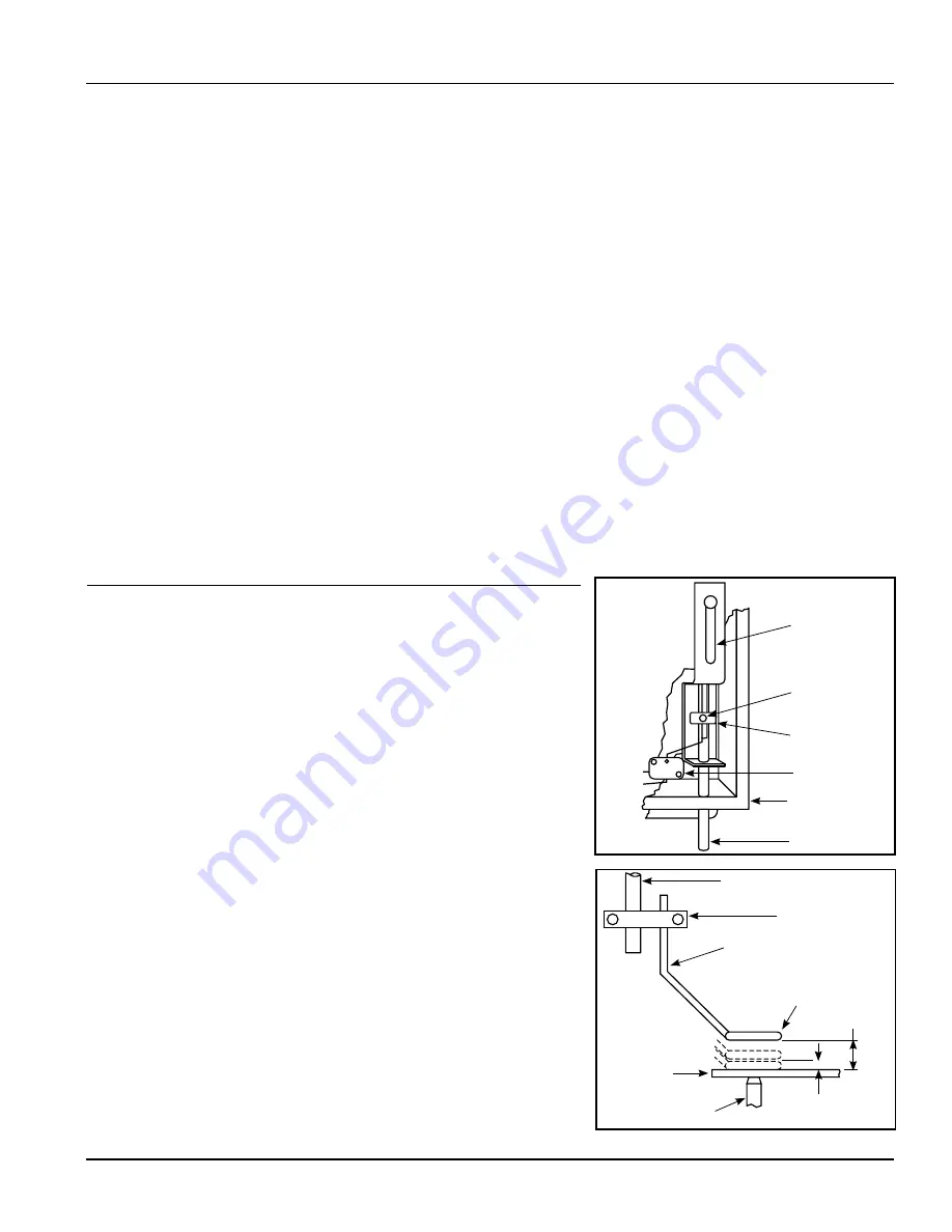
Total Travel
1/4 Inch Maximum when
Limit Switch is Actuated
Limit Switch
WIRING
(continued)
Install and wire the main disconnect switch (unless one already exists) using black wire. Follow wiring instructions shown on electrical schematics.
Make certain that this switch is capable of being locked in the “Off” position only.
Complete wiring diagrams are provided for connecting all controls and components properly. The foot switch should be installed so it is readily
available to the machine operator.
Input - Bring 120 VAC three-wire service to the Detect-A-Finger control box. Ground should be connected to Terminal 1. Connect the “Hot” side of 120
VAC to Terminal 2. Connect the common to Terminal 3.
If 120 VAC is not available on the machine, then a transformer must be incorporated to step down the line voltage. This transformer must be rated
in accordance with load requirements.
The incoming power for the Detect-A-Finger should be interfaced with the motor starter circuit so that power is only applied to the Detect-A-Finger
control box when the motor is running. Refer to the connection diagram for an example of this interface.
Output (Load) — Refer to the connection diagram. Connect the machine operating device to Terminals 4 and 5. Two jumpers may be installed, as
required, to provide the ability to control 120 VAC devices. One jumper is between Terminals 7 and 8 and the other is between Terminals 3 and 4.
Connect N.O. contact of foot switch to Terminals 6 and 7.
It is possible to isolate the output relay contact and control an external load from a separate source. Connect the external power source to Terminals
4 and 8, and the output load device to Terminals 4 and 5.
DO NOT INSTALL THE JUMPERS
.
Note: Output relay contact is rated at 230 VAC maximum.
PRELIMINARY CHECK
1.
Apply power. The power “ON” indicator should light. If not, one of the following
conditions may exist:
Main Disconnect is off.
Fuse is open.
Indicator is faulty.
Improper wiring.
Correct the problem and continue with the preliminary check.
2.
Measure the incoming voltage at Terminals 2 and 3. This should be 115 VAC ± 15%.
Shut off the power for the next step.
3.
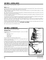
Adjust the limit switch actuator with the set screw provided. The sensing probe should
be in position over the workpiece and formed to protect the required area. Move the drop
rod manually to the point where the limit switch (in the control box) is actuated. Locate the
sensing probe at 1/4 inch or less above the workpiece. Loosen the adjustment set screw
on the limit switch actuator. Move the actuator (collar) to the point where the limit switch
is actuated and tighten the set screw. Check this adjustment periodically and before every
setup. Refer to Figures 3.1 and 3.2.
Reapply power and start the motor. The machine should be ready to cycle. Depress the
foot switch. The Detect-A-Finger rotary solenoid should energize, permitting the drop rod
to drop until the limit switch is actuated. The limit switch now energizes the control relay
and the relay contacts close, energizing the machine operating device (solenoid). The
machine should cycle once (single stroke). For successive strokes, the foot switch must
be released and depressed again.
Figure 3.2
Drop Rod
Enclosure
Drop Rod
Sensing Probe
Loop
Anvil
Piecepart
Clamp
Limit Switch Actuator
Adjustment
Set Screw
Drop Rod
Guide
SECTION 3—OPERATION
Detect-A-Finger™ Drop Probe Device-Riveter
Figure 3.1
(Continued on next page.)

