background image

Rockford Systems, LLC

20


Call: 1-800-922-7533

SECTION 6—INSTALLATION OF LONG-STROKE DROP PROBE DEVICE

Detect-A-Finger™ Drop Probe Device - Riveter

Before proceeding with the installation of this device, please use page 
25 to make a rough sketch of the location of the enclosed equipment.

Mounting 

(RKC-700 through RKC-707)

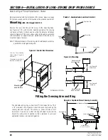
Remove the cover from the unit for access to the mounting holes. 
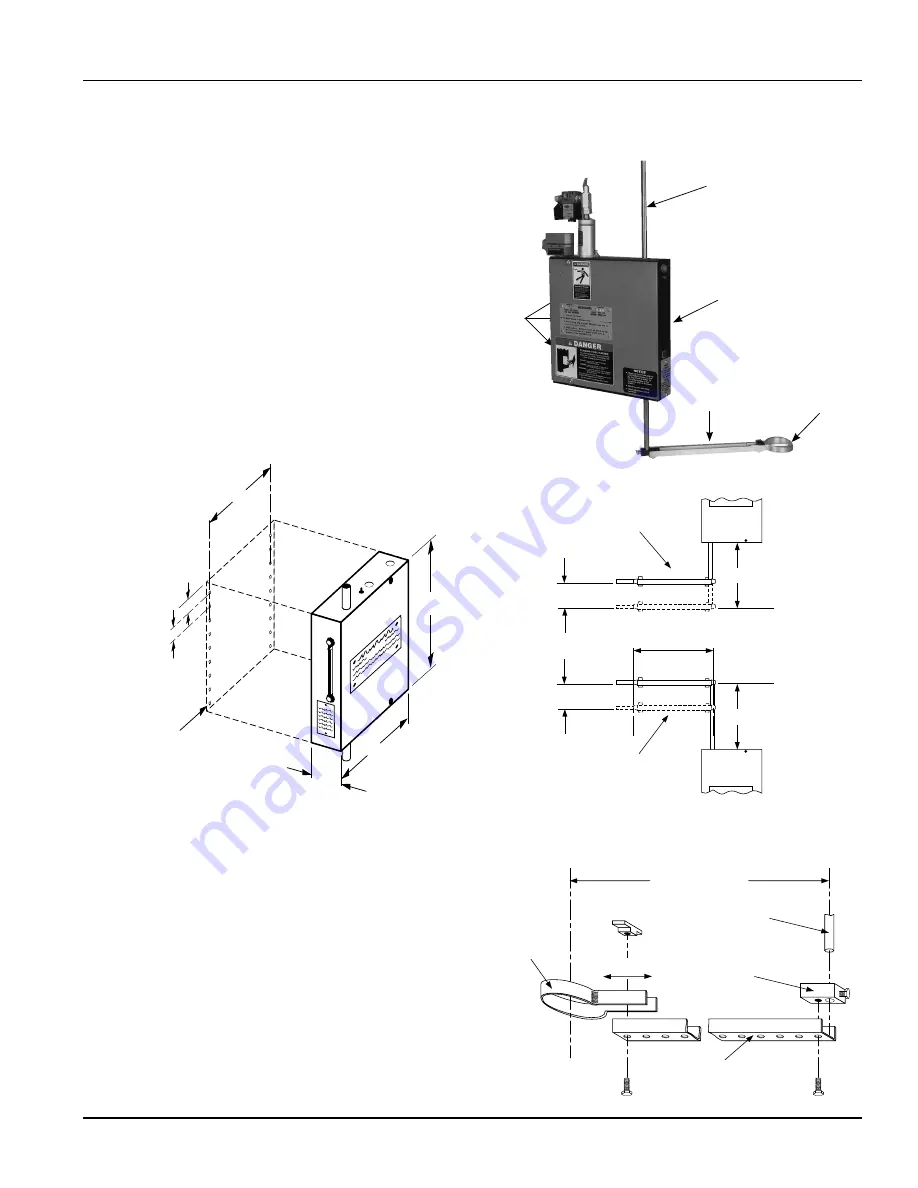
See Figure 6.1. The unit must be mounted upright so the sensing 
rod travels vertically. It should also be within the distance limitations 
shown in Figure 6.2. The cover and sensing rod should be accessible 
after installation for adjustments and maintenance. After the unit is 
mounted, replace the cover.

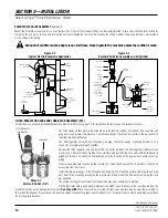
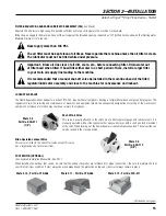
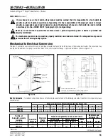
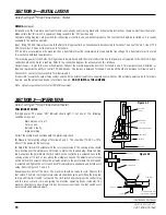
Note:   The horizontal reach of the sensing arm should be kept as short as 

possible for a more rigid sensing unit.

The standard sensing ring is a two inch (2”) circle made from a 1/16” 
x 1/2” aluminum strip. Figure 6.3 shows the parts that make up the 
sensing arm and ring unit. The arm has a series of holes at 3/4” 
increments. It can be cut so that the ring will adjust to encircle the 
hazard. An extra piece of aluminum strip is provided in case your 
application requires a special configuration.

Figure 6.3- Exploded View of Sensing Assembly

Figure 6.2- Mounting

6

7

2-

1

/

8

Mounting 

Hole Pattern

10-

1

/

4

1-

1

/

2

1

Typical

Figure 6.1 Control Box Dimensions

Use any two mounting 
holes, at least 2” apart, to 
install unit.

Use spacers or washers to 
level unit as necessary.

1

/

4

0 to 2-    Stroke

1 to 6

Vert. Reach

Stroke Up

When Mounted

Above Operation

1

/

4

0 to 2-    Stroke

1 to 6

Vert. Reach

Stroke Down

When Mounted

Below Operation

3 to 10

Horiz. Reach

10" Maximum Reach

Sensing Rod

Sensing Rod Clamp

Sensing Arm

(cut to length at installation)

adjustable

Sensing Ring

All Numbers In Inches

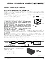
Photo 6.1 - Combination Air and Electrical Unit 

Drop Probe Rod

Control Box

Sensing Arm

Sensing Ring

Danger 

Signs

Fitting the Sensing Arm and Ring

Summary of Contents for Detect-A-Finger Drop Probe Device

Page 1: ...te www rockfordsystems com E Mail sales rockfordsystems com Manual No KSL 020 INSTALLATION MANUAL FOR DETECT A FINGER DROP PROBE DEVICE FOR RIVETERS AND OTHER MACHINES IMPORTANT PLEASE REVIEW THIS ENT...

Page 2: ...e point of operation guards and safety devices on the machine and a regularly scheduled inspection and maintenance program Rules and procedures covering each aspect of your safety program should be de...

Page 3: ...ety References OSHA S ACT AND FEDERAL REGULATIONS Since the enclosed equipment can never overcome a mechanical deficiency defect or malfunction in the machine itself OSHA Occupational Safety and Healt...

Page 4: ...12304 0739 Degreasing Liquid Small Metal Parts 12304 0537 Dies Setup and Removal of Forging Hammer 12304 0716 Drill Presses Metalworking 12304 0335 Drills Portable Reamer 12304 0497 Drop Hammers Steam...

Page 5: ...tance Never tamper with rewire or bypass any control component or safeguard on this machine Always wear safety glasses ear protection and any other personal protection equipment needed when operating...

Page 6: ...Safety Booklet A copy of Booklet No MPPS Mechanical Power Press Safety is available upon request This booklet is copied verbatim from the CFR Code of Federal Regulations and contains all relevant sect...

Page 7: ...ls become destroyed or unreadable labels MUST be replaced Contact factory immediately for replacement labels and do not operate machine until danger and warning labels are all in place Label No KST 15...

Page 8: ...pe of machinery The sensing probe that operates the limit switch is tied into the control relay in the control box and when properly wired into the machine system prevents cycling of the machine accid...

Page 9: ...alfunction or repeat strokes of the machine Before starting any installation work it is imperative that the machine s clutch is inspected and exhibits proper operation Run the machine in a normal oper...

Page 10: ...s are available to fit the Detect A Finger to various machines Part No RKC 000 mounts on the right side of a machine Part No RKC 001 mounts on the left side of a machine The drop rod exits bottom left...

Page 11: ...he total weight of the probe assembly including the clamp The action arm return spring is capable of returning 0 5 pounds maximum The user must determine and form the best shape to accommodate the par...

Page 12: ...or when voltage conditions are restored to normal These requirements are normally met by using a magnetic motor starter This starter if furnished operates with a 120 VAC coil Refer to the electrical s...

Page 13: ...he operating linkage may be connected to the air cylinder by any convenient means Be sure the rod stroke is not too long because it could cause jackknifing of the cylinder If this is a concern shorter...

Page 14: ...er cleans air that goes to the solenoid air valve and air cylinder if furnished The regulator and gauge are used to adjust air pressure The lubricator keeps the solenoid air valve or the air cylinder...

Page 15: ...nder Subpart J Section 1910 147 requires that all employers develop a complete hazardous energy control program This regulation covers the servicing and maintenance of machines and equipment where the...

Page 16: ...eadle This conversion may also require the addition of a spring to assist the return of the clutch actuation linkage A typical installation is shown in Figure 2 4 Junction Box Electric Solenoid Clutch...

Page 17: ...ed to accommodate the solenoid when required Other Installation Considerations PIPING A manual shut off valve and lockout must be installed in the air line usually just before the filter regulator lub...

Page 18: ...oad from a separate source Connect the external power source to Terminals 4 and 8 and the output load device to Terminals 4 and 5 DO NOT INSTALL THE JUMPERS Note Output relay contact is rated at 230 V...

Page 19: ...essed Terminal 8 3 with Foot Switch depressed Terminal 8 4 with Foot Switch depressed Terminal 5 4 with Foot Switch depressed 0 60 VAC 230 VAC 115 VAC 0 115 VAC 0 115 VAC 0 115 VAC 0 115 VAC 0 115 VAC...

Page 20: ...de from a 1 16 x 1 2 aluminum strip Figure 6 3 shows the parts that make up the sensing arm and ring unit The arm has a series of holes at 3 4 increments It can be cut so that the ring will adjust to...

Page 21: ...erent pressure Figure 6 4 shows the adjusting screw on the flow control valve If the cylinder operates too slow the cycle time for your machine operation could be decreased Turn the adjustment screw c...

Page 22: ...odule is a limit switch as described above which is mounted on the unit so that it will be actuated when the input module makes a complete stroke To connect the output module wire the limit switch to...

Page 23: ...Electric Output N 29 N 6 N 4 N 2 12 N 2 N 14 N 15 N 32 N 6 N 4 N 31 N 17 N 2 10 At A N 2 12 N 2 11 At C N 15 N 32 For Air Input Only Lower Cam Assembly Parts Identification Upper Cam Assembly Parts Id...

Page 24: ...21 Micro Switch Nut Operation Adjustments to Unit Once installed the unit has three simple adjustments The ring can be extended or retracted using screw 1 The height and arm of the entire test ring as...

Page 25: ...LLC Call 1 800 922 7533 25 LAYOUT OF DETECT A FINGER SYSTEM Detect A Finger Drop Probe Device Riveter MAKE YOUR SKETCH HERE FOR THE LOCATION OF THE DETECT A FINGER PARTS AND COMPONENTS TO BE INSTALLED...

Page 26: ...1 2 x 3 KSC 154 Detect A Finger Label Front Cover KSL 051 Booklet Mechanical Power Press Safety MPPS FAB Catalog Safeguarding Fabricating Machines SFM Catalog Shields for Machinery Part No Description...

Page 27: ...id Complete this form and send with material to 4620 Hydraulic Road Rockford IL 61109 2695 Make sure the R M A Number is plainly identified on the outside of the shipping container Company Address Cit...

Page 28: ...DAFRIM 0717 4620 Hydraulic Road Rockford Illinois 61109 Toll Free 1 800 922 7533 USA Only Phone 815 874 7891 Fax 815 874 6144 Web Site www rockfordsystems com E Mail sales rockfordsystems com...

Reviews: