Rockford Systems, LLC
22
Call: 1-800-922-7533
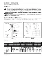
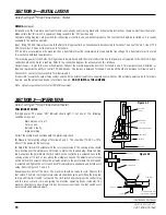
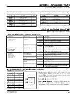
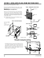
SECTION 6—INSTALLATION OF LONG-STROKE DROP PROBE DEVICE
Detect-A-Finger™ Drop Probe Device - Riveter
ELECTRICALLY-OPERATED DEVICES (PART NOS. RKC-704, RKC-705, RKC-706, AND RKC-707)
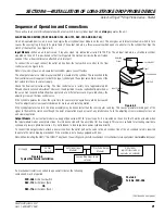
On electrically-operated devices, air is still required to operate the air cylinder input module on the unit. On these units, the air cylinder is fitted with
a 115 VAC electric solenoid control valve, which is connected to the electric foot switch. Once this valve energizes the internal mechanism, the
sensing ring drops to its preset point. The output module is an enclosed limit switch with capacity of 15A, 125 VAC suitable for operating a tripping
solenoid or solenoid air valve. (See Figure 6.7.)
Note: Different voltages are available, please consult factory.
Input Module -
To connect the input, attach an air
line (60 to 120 PSI) from the air supply to the flow
control valve on the cylinder. Refer to the air input
instructions, on the previous page, if adjustments
are necessary. Next, connect the foot switch so it
operates the electric solenoid control valve. Please
refer to the wiring diagram in Figure 6.6.
Output Module -
The electric output module is a
limit switch, as described above, which is mounted
on the unit so that it will be actuated when the input
module makes a complete stroke. To connect the
output module, wire the limit switch to operate the
machine control as shown in Figure 6.6.
If a mechanical riveter is converted to an electrically-operated riveter, the following components may be required:
CTD-065
Heavy-Duty Electric Foot Switch (See pages 15 - 16.)
OR
CTD-066
Light-Duty Electric Foot Switch (See pages 15 - 16.)
RCL-040
1/4” Filter-Regulator-Lubricator (See pages 14 - 15.)
RCD-006
Solenoid Air Valve Assembly (See pages 13 - 14.)
Air Cylinder
(Push or Pull) (See page 13.)
OR
Electric Solenoid
(Push or Pull) (See pages 16 - 17.)
Note: If different inputs or outputs are required for your application, please consult factory for pricing and part numbers.
Electric Solenoid
(which trips clutch)
SW-2
L1
L1
1-SOL
To Machine Control
SW-1
GND
115 VAC, 60 HZ
SW-1 = Foot Switch N.O. Contact
SW-2 = Enclosed L.S. N.O. Contact
1-SOL = Solenoid Valve (N.C. Contact)
Figure 6.6 - Basic Wiring Diagram
Air Supply
Air Cylinder (Input
Module)
Electric
Supply
Electric Foot
Switch
Solenoid Control Valve (Input
Module)
Limit Switch
(Output Module)
Solenoid Air
Valve
Air Cylinder
(which trips clutch)
Sensing Ring drops to
preset point
OR
Filter-Regulator-
Lubricator
Figure 6.7
Typical Electrical/Pneumatic Installation
(Continued on next page.)

