Rockford Systems, LLC
Call: 1-800-922-7533
9
SECTION 2—INSTALLATION
Detect-A-Finger™ Drop Probe Device - Riveter
Preliminary Steps Before Installation
(continued)
The operator must be protected from all hazards. All applicable sections of OSHA Section 1910.212, General Machine
Safeguarding, and ANSI B154.1 for Rivet Setting Equipment, must be complied with on all machines where this equipment
is installed.
The Detect-A-Finger controls are applicable on most types of riveting, eyeletting, staking and similarly operated assembly
and fastening machines. The function of the Detect-A-Finger device, when properly installed, adjusted and maintained,
is to keep the operator from inadvertently cycling the machine with fingers in the point of operation. The Detect-A-Finger
control does not incorporate single stroke capability. This control only provides an interface between the clutch actuator
and the trip control operating means which will not allow stroke initiation unless the area being probed is cleared of all
unwanted obstructions. To accomplish this protection, the Detect-A-Finger must be properly installed on the machine and
the device must be properly maintained and adjusted by the user. A properly designed sensing probe must be used and
additional sensing probe safeguarding must be provided where applicable. This device does not protect the operator if
fingers are placed above the sensing probe. This device cannot prevent clutch or machine malfunction or repeat strokes
of the machine.
Before starting any installation work, it is imperative that the machine’s clutch is inspected and exhibits proper operation.
Run the machine in a normal operating sequence to determine proper operation. Do not install the Detect-A-Finger on
a machine that does not function properly. When the machine is operating satisfactorily, shut off the power with the
disconnect switch and do not operate the machine again until installation is complete. Use of a lockout device and padlock
on the disconnect handle must be used during this period.
The maintenance and inspection section in this manual cannot be all-inclusive for maintaining machines. Always refer
to the original machine manufacturer’s maintenance manuals or owner’s manual. If you do not have an owner’s manual,
please contact the original equipment manufacturer.
Specifications and Operating Data
CONTROL BOX
Part Number
..................................................RKC-000 or RKC-001
Fuse
.............................................................................. 313 Series,
3AG, 3 Amps, ..................................................................................
.............................................................................. 250V, Slow Blow
Input Voltage
....................................... 115 + 15% VAC, 50/60 Hz
Operating Current
............................................... 0.8 Amps Typical
Output Relay Ratings
Resistive
General Use
10A 110VAC 7.5A 110VAC
7.5A 220VAC 5A 220VAC
10A 30VDC
Operating Current
............................................... 3.0 Amps Typical
Duty Cycle
.............................................25% (10 Second Maximum
........................................................................Continuous On-Time)
Stroke
.........................Travel Adjustable to 1.75 (1-3/4) Inches Max.
Mechanical Life
................................. Relay - 10 Million Operations
........................................... Rotary Solenoid - 100 Million Operations
Weight
...............................................................................3.5 Lbs.
SENSING PROBE (UNFORMED)
Part Number
..................................................................... FCT-030
Wire Size
................................................156 Dia. x 18 inches Long
Materia
.................................................... Aluminum Rod (Standard)
Total Weight
........................................ (Including Probe and Clamp)
............................................................. 0.5 lbs. Maximum Allowable
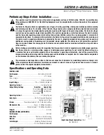
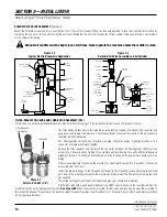
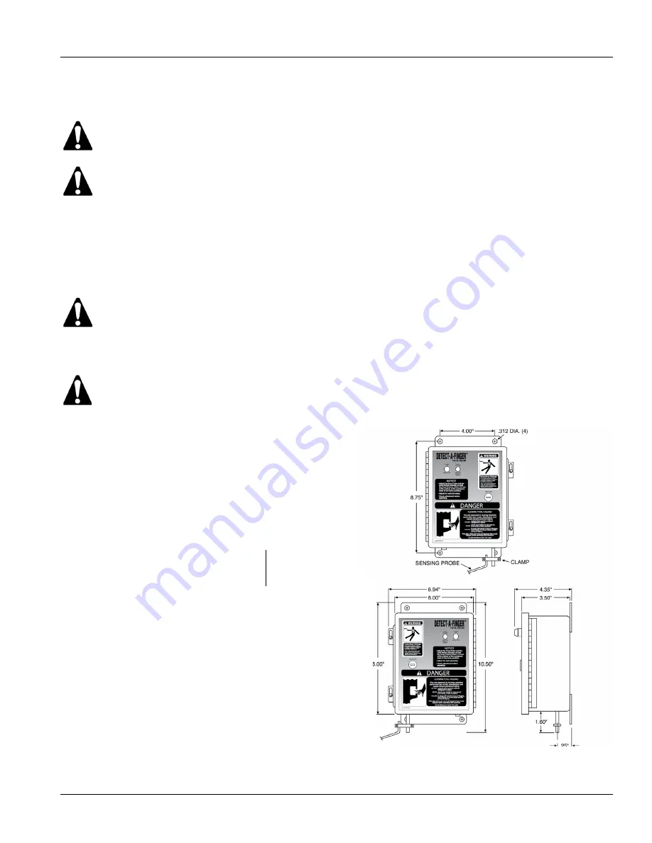
Left Side Mount
Control Box
(Part No. RKC-001)
Right Side Mount Control Box
(Part
No. RKC-000)


