background image

7

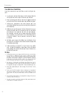
Installation Considerations

Before beginning any installation, follow these simple rules:

1.  Be sure to carefully read and understand the instructions 

before attempting to install these speakers.

2.  For easier assembly, we suggest you run all wires prior to 

mounting your speakers in place.

3.  Use high quality connectors for a reliable installation and 

to minimize signal or power loss.

4.  Think before you drill! Be careful not to cut or drill into gas 

tanks, fuel lines, brake or hydraulic lines, vacuum lines or 

electrical wiring when working on any vehicle. If installation 

in a boat, take care not to cut or drill through the main hull.

5.  Never run wires underneath the vehicle. Running the wires 

inside the vehicle or hull area provides the best protection.

6.  Avoid running wires over or through sharp edges. Use 

rubber or plastic grommets to protect any wires routed 

through metal, especially the firewall.

Mounting

1.  Determine where the speakers will be mounted. Ensure an 

area large enough for the speaker to mount evenly. Be sure 

that the mounting location is deep enough for the speaker 

to fit; if mounting in a door, operate all functions (windows, 

locks, etc.) through their entire operating range to ensure 

there is no obstruction.

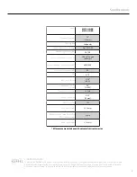
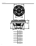
2.  Refer to the specification chart to determine the proper 

diameter hole to cut for your speaker model. Cutting and 

mounting templates can be found at www.rockfordfosgate.

com.

3.  Mark the locations for the mounting screws. Drill the holes 

with a 1/8” bit.

4.  Feed the speaker wires through the cutout and connect to 

the speaker terminals. Be sure to observe proper polarity 

when connecting the wires. The speaker’s positive terminal 

is indicated with a “+”.

5.  Fit the trim ring over the speaker and mount into place 

using the four (4) screws that are provided.

6.  Tighten the screws until the speaker is snug in place to 

prevent rattling. Do not over tighten the screws.

Installation

Summary of Contents for Element Ready M2D2-10I

Page 1: ...81 United States Direct 480 967 3565 Toll Free 800 669 9899 rockfordfosgate com 013020 1230 73054 01 D Printed In China M2D4 10I M2D4 10IB M2D2 10I M2D2 10IB Installation assistance available at ELEME...

Page 2: ...ons in this manual If you feel unsure about installing this system yourself have it installed by a qualified Rockford Fosgate technician Before installation disconnect the battery negative terminal to...
Page 3: ...tomers All measurements taken with voice coils wired in series Model M2D2 10I IB M2D4 10I IB Nominal Diameter 10 254mm Description Subwoofer Nominal Impedance Ohms 2 or 4 DVC Frequency Response Hz 20...

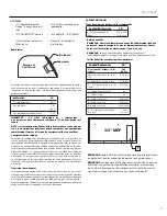
Page 4: ...l Diameter A 11 5 293mm Screw Mounting Diameter B 10 16 258mm Mounting Screw Angle C 6X60 Overall Height D 6 45 163 8mm Mounting Depth E 4 46 113 3mm Cut out Diameter F 8 9 225mm Grill Height G 2 50 8...

Page 5: ...5 Diagrams Sport Grill Stainless Steel Grill...

Page 6: ...ber of woofers and the impedance of your amplifier Subwoofer Crossovers There are two operational types of crossovers passive and active Passive crossovers coils or inductors are placed on the speaker...

Page 7: ...wires routed through metal especially the firewall Mounting 1 Determine where the speakers will be mounted Ensure an area large enough for the speaker to mount evenly Be sure that the mounting locatio...

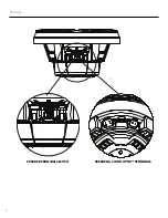
Page 8: ...8 illus 4 1 SPEAKER TERMINAL SWITCH SPEAKER COLOR OPTIX TERMINALS Wiring...

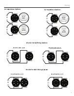
Page 9: ...ce Options Woofer Series Wiring Options D2 with Switch on 4 D2 with Switch on 1 D4 with Switch on 8 D4 with Switch on 2 Woofer Parallel Wiring Options 2 2 8 8 1 4 4 1 4 4 2 2 2 8 1 1 4 4 2 Wiring 1 4...

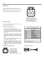
Page 10: ...o the specification to determine the size of fuse not included needed COLOR OPTIX Wiring If not using the PMX RGB follow the diagrams below for proper pin out and hard wiring instructions COLOR OPTIX...

Page 11: ...re l ampli et le haut parleur Une transition active est un filtre lectronique qui s pare le signal audio aliment aux diff rents amplis Pour une perfor mance optimale de subwoofer nous recommandons d u...

Page 12: ...plastique pour prot ger tous les fils achemin s travers le m tal en particulier le pare feu Montage 1 D terminez o les enceintes seront mont es Assurez vous que la surface de l enceinte est suffisamm...

Page 13: ...13 COMMUTATEUR DE BORNE DE HAUT PARLEUR BORNES DE HAUT PARLEUR ET COLOR OPTIX illus 3 1 C blage...

Page 14: ...1 4 4 2 2 4 2 4 4 2 D4 Options d imp dance D2 Options d imp dance Options de c blage en s rie de woofer D2 avec commutateur sur 4 D2 avec commutateur sur 1 D4 avec commutateur sur 8 D4 avec commutate...

Page 15: ...le PMX COLOR OPTIX Voir le diagramme de c blage COLOR OPTIX pour les options de c blage Rockford recommande un fil d un calibre minimum de 20 lors du raccordement lectrique des haut parleurs COLOR OPT...

Page 16: ...ivos de cruces pasivos y activos Los cruces pasivos bo binas o inductores se colocan en los cables del altavoz entre el amplificador y el altavoz Un cruce activo es un filtro electr nico que separa la...

Page 17: ...v s del metal especialmente el firewall Montaje 1 Determine d nde se montar n los altavoces Aseg rese de tener un rea lo suficientemente grande para que el altavoz se monte de manera uniforme Aseg res...

Page 18: ...18 Cableado INTERRUPTOR DE TERMINAL DE ALTAVOZ TERMINALES DE ALTAVOZ Y DEL COLOR OPTIX ilus 3 1...

Page 19: ...4 4 2 2 4 2 4 4 2 Opciones de impedancia D4 Opciones de impedancia D2 Opciones de cableado en serie para el woofer D2 con el interruptor en 4 D4 con el interruptor en 1 D4 con el interruptor en 8 D4 c...

Page 20: ...NO est utilizando el PMX COLOR OPTIX Consulte la tabla de cableado de COLOR OPTIX para ver las opciones de cableado Rockford recomienda un cable de calibre 20 m nimo al cablear sus altavoces COLOR OPT...

Page 21: ...agramm das der Wooferanzahl und der Impe danz Ihres Verst rkers entspricht Subwoofer Crossover Frequenzweichen Es gibt zwei Crossover Arten passive und aktive Passive Crossover Spulen oder Induktoren...

Page 22: ...l verlegten Dr hte insbesondere die Firewall zu sch tzen Montage 1 Bestimmen Sie wo die Lautsprecher montiert werden sollen Stellen Sie sicher dass der Bereich gro genug ist damit der Lautsprecher gle...

Page 23: ...23 Verkabelung SCHALTER DER LAUTSPRECHERANSCHL SSE LAUTSPRECHER UND COLOR OPTIX AN SCHL SSE Abb 3 1...

Page 24: ...8 1 4 4 1 4 4 2 2 4 2 4 4 2 D4 Impedanzoptionen D2 Impedanzoptionen Serienverkabelungsoptionen f r Woofer D2 mit Schalter auf 4 D2 mit Schalter auf 1 D4 mit Schalter auf 8 D4 mit Schalter auf 2 Optio...

Page 25: ...en Siehe COLOR OPTIX Verkabelungstabelle f r Verkabelungsoptionen Rockford empfiehlt eine Kabelst rke von mindestens 20 Gauge f r die Festverdrahtung Ihrer COLOR OPTIX Lautsprecher COLOR OPTIX Lichter...

Page 26: ...mero di woofer e all impedenza dell amplificatore Crossover dei subwoofer Ci sono due tipi di crossover passivo e attivo I crossover passivi bobine o induttori sono posti sui fili dell altoparlante tr...

Page 27: ...ti attraverso il metallo in particolare il firewall Montaggio 1 Determina dove verranno montati gli altoparlanti Garantire un area sufficientemente ampia per il montaggio uniforme del diffusore Assicu...

Page 28: ...28 Cablaggio INTERRUTTORE TERMINALE DELL ALTOPARLANTE ALTOPARLANTE E TERMINALI COLOR OPTIX illus 3 1...

Page 29: ...1 2 8 4 1 4 4 2 2 4 2 4 4 2 Opzioni impedanza D4 Opzioni impedanza D2 Opzioni di cablaggio in serie del woofer D2 con interruttore su 4 D2 con interruttore su 1 D4 con interruttore su 8 D4 con interr...

Page 30: ...lare un fusibile non incluso sul cavo giallo da 12 Volt quando NON si usa il PMX COLOR OPTIX Vedi la tabella di cablaggio COLOR OPTIX per le opzioni di cablaggio Rockford consiglia un filo di minimo 2...

Page 31: ...31 NOTES...

Page 32: ...Rockford s discretion What is Not Covered 1 Damage caused by accident abuse improper installation operations theft water on non Element Ready products 2 Any cost or expense related to the removal or r...

Reviews: