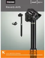
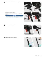
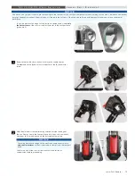
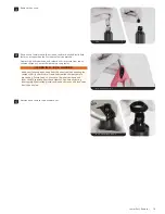
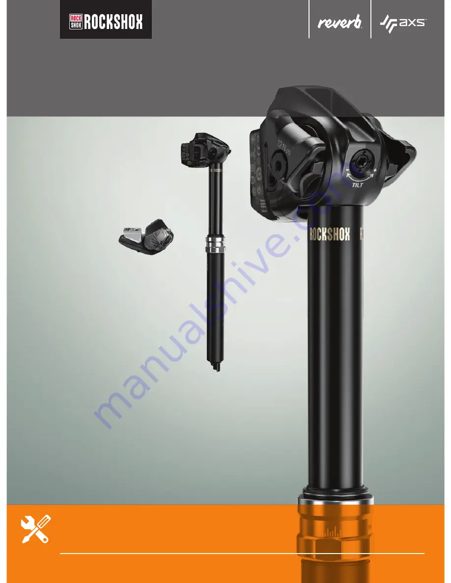
RockShox Reverb AXS 2020, Service Manual
The RockShox Reverb AXS 2020 is a cutting-edge wireless dropper post for your mountain bike. Ensure optimal performance with the free Service Manual available for download from 88.208.23.73:8080. This manual provides detailed instructions for maintenance and troubleshooting, keeping your ride smooth and efficient. Upgrade your biking experience today.
Share
Download


Reviews:
No comments
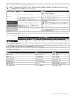
Related manuals for Reverb AXS 2020

X Series
Brand: Tailfin Pages: 4

M5
Brand: VDO Pages: 91

C210
Brand: Iget Pages: 7

KISS
Brand: Hamax Pages: 74

C800
Brand: DAPU Pages: 4

Canopy
Brand: Larry vs Harry Pages: 20

G5
Brand: Xplova Pages: 13

City
Brand: Babboe Pages: 7

Curve
Brand: Babboe Pages: 7

EC
Brand: Cane Creek Pages: 2

Bicycle Accessories
Brand: Baby Jogger Pages: 20

C965
Brand: BAFANG Pages: 18

DP C240.CAN
Brand: VANPOWERS Pages: 23

AP20
Brand: Tailfin Pages: 8

Varia
Brand: Garmin Pages: 26

Varia
Brand: Garmin Pages: 33

Varia
Brand: Garmin Pages: 167

NEO
Brand: Garmin Pages: 14


