background image

16

Rockwell Automation Publication 1441-UM002A-EN-P - May 2011

Chapter 2

        Bump Test Extension Module

Set Up Bump Test 
Measurements

Follow these steps to configure the parameters for the measurement. 

1.

Connect the transducer to the Dynamix 2500 data collector. 

2.

Attach the transducer to the machine case or structure.

3.

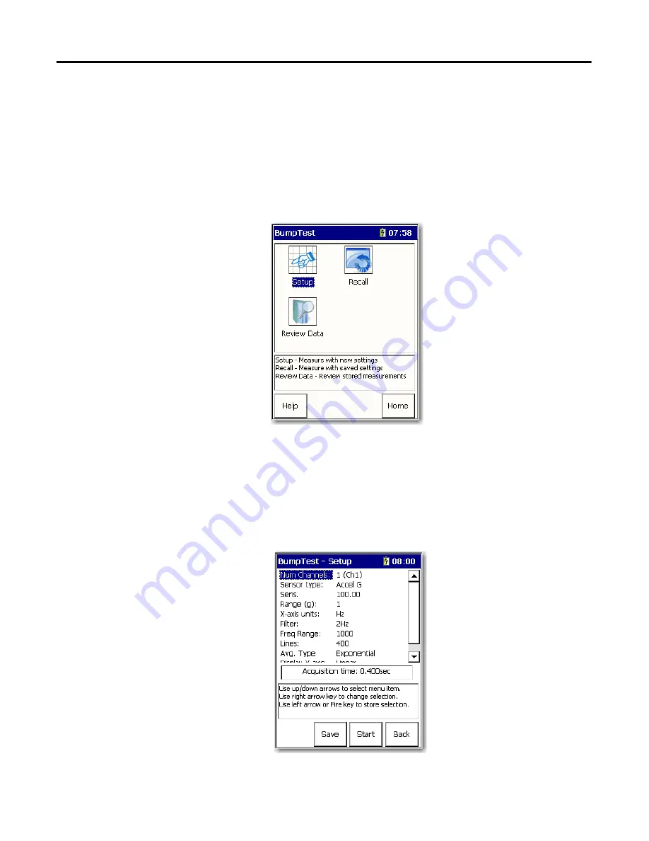
Select Bump Test on the Main Menu and press Enter.

The Bump Test screen appears. 

Setup displays the Bump Test setup parameters and begins data 
collection.

Recall lets you recall previously saved Bump Test settings to perform 
another Bump Test using the same settings. 

Review Data lets you review saved Bump Test data.

4.

Select Setup and press Enter to set up the Bump Test parameters and begin 
to collect data.

Save – Saves the current bump 
test settings. Enter a filename 
to identify the bump test 
settings.

Start – Take bump test data 
using the current settings.

Back – Returns you to the Bump 
Test menu.

Summary of Contents for 1441-DYN25-MBMP

Page 1: ...User Manual Bump Test Extension Module for the Dynamix 2500 Data Collector Catalog Number 1441 DYN25 MBMP ...

Page 2: ...sumed by Rockwell Automation Inc with respect to use of information circuits equipment or software described in this manual Reproduction of the contents of this manual in whole or in part without written permission of Rockwell Automation Inc is prohibited Throughout this manual when necessary we use notes to make you aware of safety considerations Allen Bradley Rockwell Software Rockwell Automatio...

Page 3: ...sion Modules 7 Uninstall Extension Modules 10 Manage Extension Modules 12 Extension Module Battery Status Indicators 13 Chapter 2 Bump Test Extension Module Set Up Bump Test Measurements 16 Collect Bump Test Measurements 19 Save a Bump Test Setup and Measurement 20 Recall a Setup 21 Review Bump Test Measurements 23 Save Files to Your Computer 25 Back Up Your files 26 Delete Bump Test Files 28 Inde...

Page 4: ...4 Rockwell Automation Publication 1441 UM002A EN P May 2011 Table of Contents Notes ...

Page 5: ...s you take 3 and 4 channel magnitude time waveform spectra and Offroute measurements 1441 DYN25 MBMP Bump Test The bump test or hammer test determines the natural frequencies of a machine or a structure 1441 DYN25 MBAL Balancing The balancing test resolves single plane two plane and static couple balances with high precision 1441 DYN25 MFRF Frequency Response Function The FRF test lets you determi...

Page 6: ...r the Dynamix 2500 Data Collector User Manual publication 1441 UM005 Describes how to use the data collector as a data recorder for real time data acquisition for post processing and analysis Run Up Coast Down Extension Module for the Dynamix 2500 Data Collector User Manual publication 1441 UM006 Describes how to record and analyze data from intermittent events and transient vibration signals from...

Page 7: ...or This makes the extension module available to be transferred between units Follow these instructions to install an extension module 1 Open the base cover at the bottom of the Dynamix 2500 data collector 2 Place the extension module Secure Digital SD card contact side up into the unit until it is firmly seated in place 3 Close the base cover Topic Page Install Extension Modules 7 Uninstall Extens...

Page 8: ... Modules 4 Apply power to the data collector 5 From the Main menu choose Setup Utility and press Enter 6 Press 0 Shift to display the second set of functions The Extension Manager function remains on the screen for about three seconds after releasing the 0 Shift 7 Press F1 Extn Mgr Extension Manager ...

Page 9: ...rs showing the current extension module installations 8 Press 0 Shift to display the Install Extension function 9 Press F2 Install to install the new extension module When the installation is complete a confirmation prompt appears 10 Press F4 OK The new extension module appears in the list 11 Press F4 Esc to exit the Extension Manager screen ...

Page 10: ...tility screen to display the Extension Manager function The Extension Manager function remains on the screen for about three seconds after releasing the 0 Shift 2 Press F1 Extn Mgr The Extension Manager screen appears 3 Select the extension module you want to uninstall and press F3 Select F3 Select toggles the selection on and off Extension Manager This screen lists the extension modules currently...

Page 11: ...the extension module 7 Press F4 Esc to exit the Extension Manager screen IMPORTANT The extension module is uninstalled and the license on the card is released so that the card can be used to install the extension module on another Dynamix 2500 data collector If the installation card is not inserted in the data collector and no card is found or the card does not have the extension module license fo...

Page 12: ... function The Extension Manager function should remain on the screen for approximately three seconds after releasing 0 Shift 2 Press F1 Extn Mgr The Extension Manager screen appears The Extension Manager displays a list of installed extension modules The F2 function key toggles between Hide and Show depending on if the selected extension module is hidden IMPORTANT Once an extension module is hidde...

Page 13: ...If you want to show or hide multiple extension modules simultaneously select each extension module and press F3 Select A checkbox appears next to each selected extension module If you select multiple extension modules and some are hidden while others are shown F2 Show Hide reflects the status of the selected extension module Table 1 Extension Module Battery Icon Descriptions Battery Icon Meaning B...

Page 14: ...14 Rockwell Automation Publication 1441 UM002A EN P May 2011 Chapter 1 Installing Optional Extension Modules Notes ...

Page 15: ...to the impact peaks will result and pinpoint the object s natural frequencies The Dynamix 2500 data collector can be used to capture this frequency response and illustrates the resonant frequencies Vibration forces transmitted by rotating machines often excite natural resonance in structures attached to the machine When these structural resonances appear vibration levels are amplified and can resu...

Page 16: ... press Enter The Bump Test screen appears Setup displays the Bump Test setup parameters and begins data collection Recall lets you recall previously saved Bump Test settings to perform another Bump Test using the same settings Review Data lets you review saved Bump Test data 4 Select Setup and press Enter to set up the Bump Test parameters and begin to collect data Save Saves the current bump test...

Page 17: ...ed sensor type determines available options and engineering units for subsequent setup fields Accel G default Accel m s2 Vel IPS Vel mm s Disp um Disp mil Volts AC Volts DC Sensor Sensitivity Enter transducer sensitivity in millivolts mV per Engineering Unit EU typically 100 mV g mV EU Range EU Full Scale Define the spectrum s maximum full scale amplitude value 1 default 2 5 10 20 50 100 200 500 1...

Page 18: ... and consumes more storage memory 400 default 100 200 400 800 1600 3200 6400 12800 25600 Avg Type Specify the Peak Hold averaging The data collector holds the highest spectral peak for each hammer hit For exponential averaging the data collector averages multiple hits to minimize the noise level however you must pause the averaging process after the last hit Pk Hold Exponential default Display Y a...

Page 19: ...device hit the machine Notice the natural frequency spectral peaks displayed on the screen 3 Commence bump test hammer hits to display natural frequency spectral peaks 4 Move the cursors to identify natural frequencies Press F3 Pause to pause the data on the screen Pause toggles to the Start function Press F3 Start to start collecting data again The Left and Right arrows move the cursor across the...

Page 20: ...500 data collector stores bump test measurements in comma separated value format csv in the Internal Disk Analyzer folder These csv files can be viewed with the Microsoft Excel software Follow these steps to save a file 1 Take a reading 2 Press F2 Save The Bump Test Save Data screen appears Table 3 Significant Peak Functions On pressing H Function Once Enables the harmonic cursors Press the Left a...

Page 21: ...estamp 5 When the entry is complete press F2 OK Recall a Setup You can recall a previously saved setup and use it to record another measurement The setup may have been saved only as a setup or may have been saved with the recorded data See Save a Bump Test Setup and Measurement on page 20 Follow these instructions to recall a Bump Test setup 1 Connect the transducer to the Dynamix 2500 data collec...

Page 22: ...t screen appears 4 Select Recall and press Enter The Bump Test Load Setup screen appears 5 Select the filename test settings that you want to recall reload and press F3 Open The Bump Test Setup screen appears 6 You can edit the settings or start collecting more data See Set Up Bump Test Measurements on page 16 ...

Page 23: ...the Dynamix 2500 data collector 1 Select Review Data on the Bump Test screen and press Enter The Bump Test Review Data screen appears 2 Select a measurement for review and press F3 Open The measurement appears 3 Press F2 Prev and F3 Next to display the previous or next measurement 4 Press F1 Print if you what to create a bmp file that is stored on the SD storage card or internally ...

Page 24: ...Extension Module 5 When finished press F4 Back to return to the Review Data screen to review additional stored measurements 6 Select the file that you want to review and press F3 Open TIP To delete previously saved bump test data select the file and press 0 Shift and then F4 Delete ...

Page 25: ...nc software 1 Connect the instrument with the USB cable to your computer ActiveSync automatically senses the connection and displays the Connected Synchronized message See the Dynamix 2500 Data Collector User Manual publication 1441 UM001 for information about ActiveSync communication 2 From the File menu select Explore 3 From the Windows Explorer window copy the stored measurement files csv files...

Page 26: ...ata screen use the Up and Down arrows to select a measurement for backup or select the all option to back up all measurments 3 Press 0 Shift The Backup function appears 4 Press F1 Backup IMPORTANT The back up option can erase existing files on the SD storage device It is recommend that a blank SD card is used for backing up your files The SD storage card should not be disconnected in hazardous are...

Page 27: ... prompts whether to format the card prior to backup answer appropriately All selected measurement files are copied to the SD card and a Backup Complete message appears 5 Press F2 OK to return to the Review Data screen 6 Remove the card and store in a safe place IMPORTANT When you answer Yes all data is deleted ...

Page 28: ...the Dynamix 2500 data collector 1 Select Review Data saved measurements or Recall saved settings and press Enter 2 On the Bump Test Review Data screen select a file When the file is listed on the root of the data collector it is saved internally If you want to delete a file on the storage card either open the folder and delete the file or you can use the ActiveSync software ...

Page 29: ...1 UM002A EN P May 2011 29 Bump Test Extension Module Chapter 2 3 Use 0 Shift on any Recall screen to display the delete function 4 Select a file and press 0 Shift 5 Press F4 Delete The deleting file popup appears 6 Press F2 Yes or F3 No ...

Page 30: ...30 Rockwell Automation Publication 1441 UM002A EN P May 2011 Chapter 2 Bump Test Extension Module Notes ...

Page 31: ...ng data 23 save measurement 20 save setup 20 C channels 17 D delete data 28 E Extension Manager 7 install module 7 uninstall 7 10 extension module hide and show 12 license 11 not visible 12 F fatigue 15 FFT 17 filter 17 frequencies 15 frequency 19 range 17 H hammer test 15 harmonic cursors 20 L lines 18 P parameters 16 peak hold 18 R range 17 recall 18 resolution 18 reviewing data bump test 23 S s...

Page 32: ...32 Rockwell Automation Publication 1441 UM002A EN P May 2011 Index Notes ...

Page 33: ......

Page 34: ...urs of installation review the information that is contained in this manual You can contact Customer Support for initial help in getting your product up and running New Product Satisfaction Return Rockwell Automation tests all of its products to ensure that they are fully operational when shipped from the manufacturing facility However if your product is not functioning and needs to be returned fo...

Reviews: