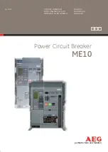
1397 Inverting Fault Circuit Breaker
9
1397-5.29 September, 1998
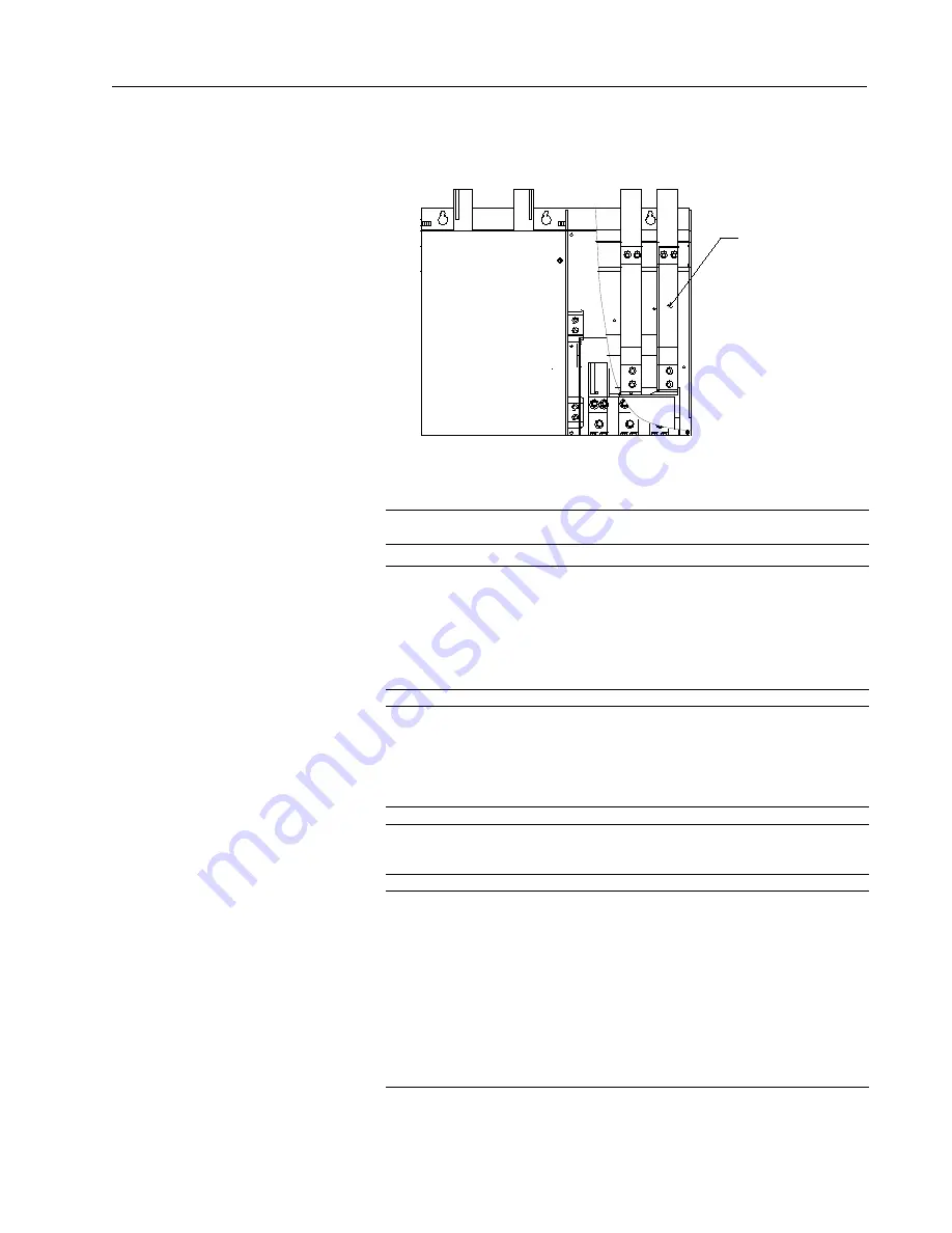
Figure 7.
Removable Link Location
Removable
Link
A2/S1
DBR
S2
A1
TOP VIEW
Wire Assembly
Connections
❐
1
Remove the two screws and open the drive cover (see Figure 8).
❐
2
Locate and remove the spade connector from terminal A2 on the
Power Interface board, located in the center of the drive. Cap this
lead with the male spade connector supplied in this kit. (Refer
to Figure 8 for the location of the Power Interface board and for
the location of terminal A2.)
❐
3
Attach the spade connector on the A2 FDBK wire lead to terminal
A2 on the Power Interface board. Route this wire to Inverting
Fault Circuit Breaker terminal MOT. Cut the wire to length as
required and terminate the end with the ring lug supplied in the kit.
❐
4
Connect the ring lug to terminal MOT of the Inverting Fault
Circuit Breaker as shown in Figure 9.
❐
5
Connect the spade connectors of the twisted pair harness to the
male connectors on the yellow lead and the blue/yellow striped
lead coming out of the Inverting Fault Circuit Breaker (see Figure
9). Route this harness to the bottom of the drive. Cut the wires
to length as required, and connect them to terminals 9 and 11 on
the Regulator board control terminal strip as shown in Figure 10.
If any other interlocks are required for your application, they must
be connected in series to the Customer Interlock Input (terminals
9 and 11) along with the circuit breaker.


