8
40752-195 (1)
Effective
2
/201
1
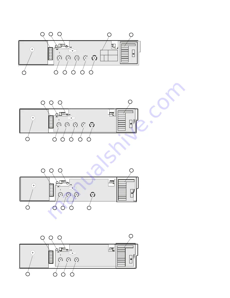
4-1 . Test Port - a test port is built into each
trip unit to allow use of a functional test kit.
The test kit performs a test of the Long Delay,
Short Delay, and Ground Fault functions.
4-2 . Test LED - to be used with a no trip
functional test. This LED is a dual function
light. As previously stated, the LED is used
as a no trip indicator when using the test port.
In normal modes, this LED indicates a high
load alarm. It will light if the continuous cur
-
rent is 95% of the setting and must be present
for a 38 second duration.
4-3 . IR - Continuous Current Setting. In
accordance with standards requirements, the
trip unit initiates a trip of the circuit breaker
within 2 hours for an overload of 135% and
will trip as a function of 12 t for higher cur
-
rents. Continuous Current Values for each
lettered setting are indicated by the chart on
the right side of the trip unit.
4-4 . tR - The number of seconds required to
trip @ 6x. For example, IR - 800A, - 2 sec
load current - 4800A (6x). The breaker will
trip in 2 seconds.
NOTE: The last two time settings vary
according to the frame as follows: 1200A -
20,24, 1250A\800A - 14,14, 1600A - 20,20.
NOTE: There is a thermal memory capacitor
that will affect the LDT time. If the breaker
has tripped on LD, this capacitor must be
discharged or it will self discharge after five
minutes. If neither one of these choices has
been done, the LD trip time will be shorter.
4-5 . Isd - Setting in multiples of IR. For
short circuit conditions that exceed the short
delay pick-up setting, the trip unit initiates a
trip after a predetermined delay.
4-6 . The - Ig (xIn) switch is the ground fault
pick-up switch and is used on the LSIG &
LSG styles to set the ground fault pick-up as a
percentage of I (Frame current). For example,
a 1200A frame with an Ig (xIn) setting of 0.4
will provide a ground fault pick-up at 480A.
4-7 . For the LSI style, the Short Delay time is
a flat response determined by the tsd/tg switch
setting of INST, 120ms or 300ms. For the LS
style, the short delay time is an 12t function.
Push to Trip
6646 C06 H01
STATUS
TEST / ALARM
6646 C05 H10
E
G
F
H
A
B
D
C
I
R
6
8
7
2
3
5
4
9
I
sd (xI
R
)
SHORT
9
12
20
15
24
2
4
10
7
t
R
(s)
LONG
B
C
D
E
F
G
H
I
J
A
STATUS
TEST / ALARM
6646 C05 H07
E
G
F
H
A
B
D
C
I
R
120
300
Inst.
t
sd (ms)
SHORT
6
8
7
2
3
5
4
9
I
sd (xI
R
)
SHORT
9
12
20
15
24
2
4
10
7
t
R
(s)
LONG
B
C
D
E
F
G
H
I
J
A
Push to Trip
6646 C06 H01
Push to Trip
6646 C06 H01
STATUS
TEST / ALARM
6646 C05 H04
E
G
F
H
A
B
D
C
I
R
.8 1.0
.2
.3
.6
.4
I
g (xIn)
GND
120
300
Inst.
t
g (ms)
GND
6
8
7
2
3
5
4
9
I
sd (xI
R
)
SHORT
9
12
20
15
24
2
4
10
7
t
R
(s)
LONG
B
C
D
E
F
G
H
I
J
A
STATUS
TEST / ALARM
t
g (ms)
t
sd
(ms)
120
K
N
Q
300
L
O
R
*
Inst.
J
M
P
Inst.
120
300
Settings
6646 C05 H01
E
G
F
H
A
B
D
C
I
R
.8 1.0
.2
.3
.6
.4
I
g (xIn)
GND
N
P
O
Q
J
K
M
L
R
t
sd /
t
g (ms)
SHORT / GND
*
6
8
7
2
3
5
4
9
I
sd (xI
R
)
SHORT
9
12
20
15
24
2
4
10
7
t
R
(s)
LONG
B
C
D
E
F
G
H
A
Push to Trip
6646 C06 H01
1
2
3
4
5
6
8
3
8A
10
11
1
2
3
10
3
4
5
6
11
9
1
2
3
10
3
4
5
11
7
1
2
3
10
3
4
5
11
4. TRIP UNIT ADJUSTMENTS


