1-4
Getting Started
Standard Drive Features
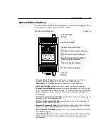
The drive features identified in the figure below apply to all models.
Standard Drive Features and Mounting Orientation
Figure 1.3
•
Hinged Finger Guard
allows easy access to line/load power terminals.
•
Ready/Fault Indicating Panel
is standard on the Bulletin 160 drive. The drive
is fully functional with this panel installed. All control functions can be
performed from TB3 (Control Terminal Block). Factory default settings cannot
be changed with this panel.
•
Fault Indicator LED
illuminates when a drive fault condition exists. Refer to
Chapter 6 for details on how to clear a fault and general troubleshooting
procedures.
•
Ready Indicator LED
illuminates when the DC bus is charged and the drive is
ready to run.
•
DC Bus Test Points
provide easy access for test probes when measuring DC
Bus voltage.
•
Cooling Fan
provides air flow across heatsink fins to prevent overheating. Not
required on .37 or .55 kW (.5 or .75 HP) ratings.
•
DIN Latch
provides an easy means for mounting the drive on standard 35 mm
DIN Rail. This feature is not available with 4.0 kW (5 HP) or 1.5 kW (2 HP)
single phase units.
Cooling Fan
DIN Latch
Status LEDs
DC+
W/T3
1
3 4 5 6 7 8 9 10 11
2
V/T2
U/T1
DC–
BR+
T/L3
S/L2
R/L1
BR–
FAULT
READY
Hinged Finger Guard
Hinged Finger Guard
Cooling
Air Flow
Ready/Fault
Indicating Panel
DC Bus Test Points
Summary of Contents for Allen-Bradley 160 SSC Series
Page 12: ...1 6 Getting Started End of Chapter ...
Page 58: ...5 20 Parameters and Programming End of Chapter ...
Page 66: ...A 4 Specifications End of Chapter ...
Page 75: ...Accessories and Dimensions B 9 Drilling Template A Figure B 10 ...
Page 76: ...B 10 Accessories and Dimensions Drilling Template B Figure B 11 ...
Page 82: ...C 6 CE Conformity End of Chapter ...
Page 87: ......

