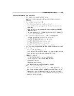
5-12
Parameters and Programming
54
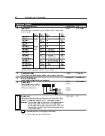
[Clear Fault]
Setting this parameter to a 1 performs a fault reset. When the fault reset function
is complete, the value is automatically set back to 0.
This parameter cannot be programmed while the drive is running.
0/1
Numeric
Value
0
55
[Memory Probe Address]
Used by Rockwell Automation field service personnel.
Numeric
Value
Numeric
Value
Numeric
Value
56
[Reset Functions]
Drive parameters and their associated defaults are reset according to the
following descriptions:
Settings:
0
Idle State
1
Reset defaults (restores all parameter settings to factory defaults).
2
Update Input Mode (restores the drive to most recent programmed
P46 - [Input Mode] setting).
After the reset/update function is complete, this parameter will set itself back to
a “0.” This parameter cannot be programmed while the drive is running.
Important:
For setting 1 only, an F48 - Reprogram Fault will occur and must be
cleared by cycling the Stop input to the drive. P46 - [Input Mode]
factory defaults to 3-wire control. If using keypad control, change
parameter setting back to a 2 to regain program keypad control,
cycle power or use P56 Setting 2 again.
0/2
Numeric
Value
0
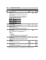
57
[Program Lock]
When set to 1, all parameters will be protected against change by unauthorized
personnel.
0/1
Numeric
Value
0
58
[Internal Frequency]
When P59 - [Frequency Select] is set to a 1, this parameter will provide the drive
frequency command. This parameter will change the frequency command in “Real
time” using the up/down arrow keys. Maximum value is set in P33 - [Maximum
Frequency].
Important:
Follow normal programming procedures. Once the desired
command frequency is reached, the Enter key must be pressed to
store this value to EEPROM memory. If the ESC key is used before
the Enter key, the frequency will return to the original value following
the normal accel/decel curve.
0.0/240.0
0.1 Hz
60.0 Hz
59
[Frequency Select]
Selects the source of the frequency command for the drive.
Settings: 0 = External frequency command from the Control Terminal Block (TB3)
1 = Internal frequency command from P58 - [Internal Frequency].
0/1
Numeric
Value
0
60
[Zero Offset]
Used to add or subtract any system offset to the analog input.
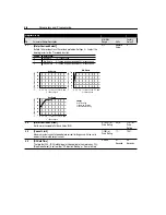
See P16 - [Analog Input] for additional information.
Important:
This parameter cannot be programmed while the drive is running.
–50.0/+ 50.0
Numeric
Value
0%
Program Group
No.
Parameter Name/Description
Min./Max.
Range
Units
Factory
Default
This parameter applies only to the Analog Signal Follower model.
Summary of Contents for Allen-Bradley 160 SSC Series
Page 12: ...1 6 Getting Started End of Chapter ...
Page 58: ...5 20 Parameters and Programming End of Chapter ...
Page 66: ...A 4 Specifications End of Chapter ...
Page 75: ...Accessories and Dimensions B 9 Drilling Template A Figure B 10 ...
Page 76: ...B 10 Accessories and Dimensions Drilling Template B Figure B 11 ...
Page 82: ...C 6 CE Conformity End of Chapter ...
Page 87: ......


