6-4
Troubleshooting
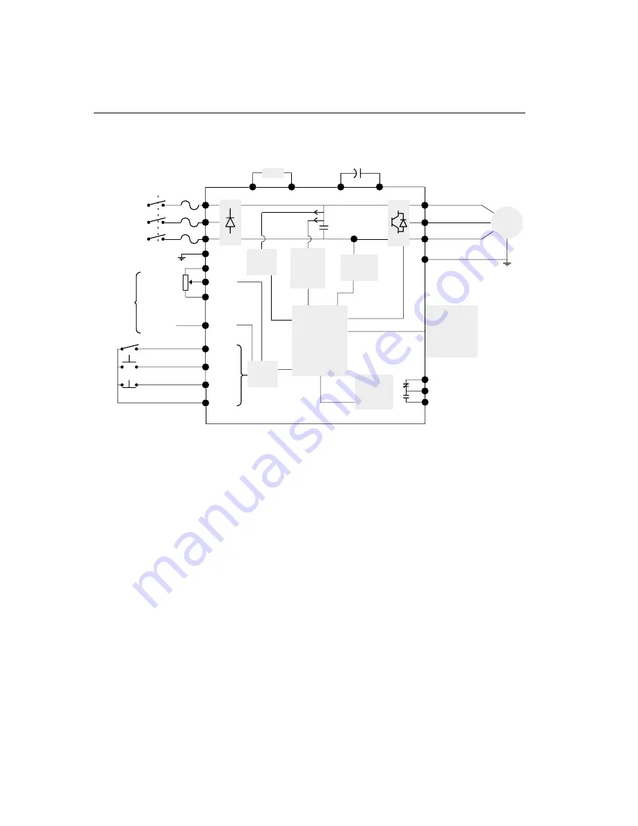
Block Diagram of Bulletin 160 Analog Signal Follower
Figure 6.3
L1/R
L3/T
L2/S
TB3 - 1
TB3 - 2
TB3 - 3
(Common)
-10 to +10V
4 - 20 mA
Common
Programable Input
Start
Reverse
TB3 - 4
TB3 - 5
TB3 - 6
TB3 - 8
TB3 - 7
or
Potentiometer
Frequency
Reference
or
Opto
Isolator
C P U
Relay
Circuitry
Program
Keypad
Module
Motor
T1/U
T2/V
T3/W
GND/PE
Current
Circuitry
Bus
Voltage
Circuitry
Control
Power
Fault Feedback
DC-
DC+
BR-
BR+
User
Programmable
Output
Capacitor Module
Brake Module
GND/PE
TB3 - 9
TB3 - 10
TB3 - 11
Summary of Contents for Allen-Bradley 160 SSC Series
Page 12: ...1 6 Getting Started End of Chapter ...
Page 58: ...5 20 Parameters and Programming End of Chapter ...
Page 66: ...A 4 Specifications End of Chapter ...
Page 75: ...Accessories and Dimensions B 9 Drilling Template A Figure B 10 ...
Page 76: ...B 10 Accessories and Dimensions Drilling Template B Figure B 11 ...
Page 82: ...C 6 CE Conformity End of Chapter ...
Page 87: ......


