background image

Rockwell Automation Publication 1606-RM002A-EN-P - March 2019

9

Power Supply - 24V, 10 A, 240 W, Three-phase Input

DC Input

Do not operate the power supply with DC input voltage.

Input Inrush Current

An active inrush limitation circuit limits the input inrush current after turn-on of 
the input voltage and after short input voltage interruptions.

The charging current into EMI suppression capacitors is disregarded in the first 
microseconds after switch-on.

Figure 6 - Typical Input Inrush Current Behavior at Nominal Load and 25 

°

C (77 

°

F) Ambient 

Temperature

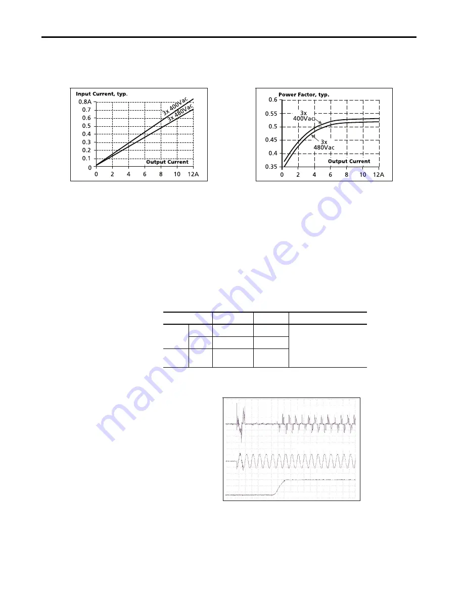
Figure 4 - Input Current versus Output Load at 24V

Figure 5 - Power Factor versus Output Load

Attribute

3x 400V AC

3x 480V AC

Description

Inrush 
current

Max

10 A peak

10 A peak

Temperature independent

Typ

4 A peak

4 A peak

Inrush 
energy

Max

0.5 A

2

s

1.5  A

2

s

Input current 1A/DIV

Input voltage 500V/DIV

Output voltage

20ms/DIV

Summary of Contents for Allen-Bradley 1606-XLE240E-3

Page 1: ...Power Supply 24V 10 A 240 W Three phase Input Catalog Number 1606 XLE240E 3 Reference Manual OriginalInstructions ...

Page 2: ...information circuits equipment or software described in this manual Reproduction of the contents of this manual in whole or in part without written permission of Rockwell Automation Inc is prohibited Throughout this manual when necessary we use notes to make you aware of safety considerations Labels may also be on or inside the equipment to provide specific precautions WARNING Identifies informati...

Page 3: ...0 Hold upTime 11 Approximate Dimensions andWeight 21 Efficiency and Power Loss 12 Accessories 22 Functional Diagram 13 Application Notes 23 Front Side and User Elements 13 Resource Description 1606 XL Power SupplyTechnical Data publication 1606 TD001 Provides specifications and certifications for the 1606 XL240E 3 power supply Industrial AutomationWiring and Grounding Guidelines publication 1770 4...

Page 4: ...r applications in harsh areas The 1606 Essential line includes all essential basic functions The devices have a power reserve of 20 included which may even be used continuously at temperatures up to 45 C 113 F Additionally the 1606 XLE240E 3 can deliver three times the nominal output current for 10 ms which helps to trip fuses on faulty output branches The power supply features 3x 380 480V AC wide...

Page 5: ...13 F ambient 60 C 140 F ambient 70 C 158 F ambient Derate linearly between 45 70 C 113 158 F Input voltage AC Mains frequency Input current AC Power factor 3x 380 480V AC 50 60 Hz 0 7 0 6 A 0 53 0 52 A 15 20 6 3x 400 480V 3x 400 480V AC inrush current 4 4 Apk 3x 400 480V Efficiency Losses 92 8 92 9 18 6 18 3W 3x 400 480V 3x 400 480V Hold up time 34 54 ms 3x 400 480V Temperature range 25 70 C 13 15...

Page 6: ...al connection Unused screw terminals should be securely tightened The device is designed for pollution degree to areas in controlled environments No condensation or frost allowed The enclosure of the device provides a degree of protection of IP20 The isolation of the device is designed to withstand impulse voltages of overvoltage category 3 according to IEC 60664 1 for corner grounded delta system...

Page 7: ...onment for use above 2000 m 6560 ft Keep the following minimum installation clearances 40 mm 1 57 in on top 20 mm 0 78 in on the bottom 5 mm 0 19 in left and right side Increase the 5 mm 0 19 in 15 mm 0 59 in in case the adjacent device is a heat source When the device is permanently loaded with less than 50 the 5 mm 0 19 in can be reduced to zero The device is designed tested and approved for bra...

Page 8: ...lation Notes Attribute 3x 400V AC 3x 480V AC Description Input current Typ 0 7 A 0 6 A At 24V 10 A per phase see Figure 4 Power factor 1 Typ 0 53 0 52 At 24V 10 A see Figure 5 Start up delay Typ 90 ms 90 ms See Figure 3 Rise time Typ 40 ms 40 ms At 24V 10 A const current load 0mF load capacitance seeFigure 3 Typ 85 ms 85 ms At 24V 10 A const current load 10mF load capacitance see Figure3 Turn on o...

Page 9: ...ions The charging current into EMI suppression capacitors is disregarded in the first microseconds after switch on Figure 6 Typical Input Inrush Current Behavior at Nominal Load and 25 C 77 F Ambient Temperature Figure 4 Input Current versus Output Load at 24V Figure 5 Power Factor versus Output Load Attribute 3x 400V AC 3x 480V AC Description Inrush current Max 10 A peak 10 A peak Temperature ind...

Page 10: ... 20 Hz 20 MHz 50 Ohms Output current Nom 12 A 1 1 This current is also available for temperatures up to 70 C 158 F with a duty cycle of 10 and or not longer than 1 minute every 10 minutes At 24V below 45 C 113 F ambient temperature 10 A At 24V below 60 C 140 F ambient temperature 7 5 A At 24V at 70 C 158 F ambient temperature 10 3 A 1 At 8V and an ambient temperature below 45 C 113 F 8 6 A At 28V ...

Page 11: ...ing Output Voltage Parallel Use Mode Typ 22V 0 4 8 23V 24V 25V 29V 26V 27V 28V 12A 10 6 2 Adjustment Range Factory setting Output Current Attribute 3x 400V AC 3x 480V AC Description Typ 34 ms 54 ms At 24V 10 A seeFigure 9 Typ 68 ms 108 ms At 24V 5 A see Figure 9 Min 28 ms 44 ms At 24V 10 A seeFigure 9 Min 56 ms 87 ms At 24V 5 A see Figure 9 Figure 9 Hold upTime versus Input Voltage Figure 10 Shut ...

Page 12: ...inal loadfor another 25 of the time 75 of the nominal load for another 25 of the time and with 100 of the nominal load for the rest of the time Typ 92 2 92 0 25 at 2 5 A 25 at 5 A 25 at 7 55 A at 10 A 3 phase operation Power losses Typ 2 3W 2 6W At 0 A 3 phase operation Typ 11 8W 11 8W At 24V 5 A 3 phase operation Typ 18 6W 18 3W At 24V 10 A 3 phase operation Typ 12 3W 11 6W At 24V 12 A 3 phase op...

Page 13: ...wer Manager Temper ature Shut down DC ok LED L2 L3 L1 Single Parallel POWER SUPPLY 1606 XLE DC 24V 10A L3 Input 3AC 380 480V DC ok 1606 XLE240E 3 L2 L1 24 28V 18WM IND CONT EQ Parallel Use Single Use QUALITY Allen Bradley C D E Letter Definition A Output terminals screw terminals two pins per pole Positive output Negative return output B Input terminals screw terminals N L Line input PE Protective...

Page 14: ...A If the current is higher use a separate distribution terminal block See Figure 16 Attribute Input and Output Type Screw termination Solid wire Max 6 mm2 Stranded wire Max 4 mm2 American wire gauge AWG 20 10 Wire diameter max including ferrules 2 8 mm 0 11 in Tightening torque recommended 1 Nm 9 lb in Wiring stripping length 7 mm 0 28 in Screwdriver 3 5 mm slotted or Phillips no 1 Figure 15 Daisy...

Page 15: ... 100 000 h 100 000 h At 24V 10 A and 40 C 104 F 3 phase Ground Fixed GF40 132 000 h 132 000 h At 24V 10 A and 25 C 77 F 3 phase Ground Benign GB25 436 000 h 423 000 h At 24V 10 A and 40 C 104 F 2 phase Ground Fixed GF40 555 000 h 572 000 h At 24V 10 A and 25 C 77 F 2 phase Ground Fixed GF25 98 000 h 98 000 h At 24V 10 A and 25 C 77 F 2 phase Ground Fixed GF25 129 000 h 129 000 h At 24V 10 A and 25...

Page 16: ...edips Dips on 3 phases EN 61000 4 11 0 of 380V AC 0 of 480V AC 0V AC 20 ms 0V AC 20 ms Criterion A Criterion A Mainsvoltagedips Dips on 2 phases EN 61000 4 11 40 of 380V AC 40 of 480V AC 70 of 380V AC 70 of 480V AC 200 ms 200 ms 500 ms 500 ms Criterion A Criterion A Criterion A Criterion A Voltage interruptions EN 61000 4 11 5 s Criterion C Powerful transients VDE 0160 Over entire load range 1550V...

Page 17: ...IEC 60664 1 altitudes 2000 6000 m 6560 ft 19685 ft and atmosphere pressures 80 47 kPa Degree of pollution 2 IEC 62477 1 non conductive Vibration sinusoidal 3 3 Tested ona DIN Rail according to IEC 60715 with a height of 15 mm 0 59 in and thickness of 1 3 mm 0 05 in 2 17 8Hz 1 6 mm 17 8 500Hz 2 g 2 hours axis IEC 60068 2 6 Shock 4 4 Tested ona DIN Rail according to IEC 60715 with a height of 15 mm ...

Page 18: ...lationbetween the operating temperature and turn off temperature since this is dependent on input voltage load and installation methods Included Input transient protection MOV Metal OxideVaristor Internal input fuse Included Not user replaceable Attribute Description Class of protection I IEC 61140 A PE Protective Earth connection is required Isolation resistance Min 500 MOhm At delivered conditio...

Page 19: ... s down Connect all input terminals together and all output poles before conducting the test When testing set the cut off current settings to the value in the table below Figure 19 Dielectric Strength It is recommended that either the pole pole or any other part of the output circuit shall be connected to the earth ground system This helps to avoid situations in which a load starts unexpectedly or...

Page 20: ...I Division 2 wiring methods of the National Electrical Code NFPA 70 and in accordance with otherlocal or national codes UL 508 Listed for use as Industrial Control Equipment U S A UL 508 and Canada C22 2 No 107 1 01 E File E56639 UL 60950 1 2nd edition Recognized for use as InformationTechnology Equipment Level 5 U S A UL 60950 1 and Canada C22 2 No 60950 1 File E168663 Applicable for altitudes up...

Page 21: ... 60715 or EN 50022 with a height of 7 5 or 15 mm 0 29 or 0 59 in Plastic Material of Housing Body aluminum alloy Cover zinc plated steel Installation Clearances Keep the following installation clearances 40 mm 1 57 in on top 20 mm 0 78 in onthe bottom 5 mm 0 19in onthe left and right sides are recommended when the device is loaded permanently with more than 50 of the rated power Increase this clea...

Page 22: ...ed in the holes of the aluminum brackets The order number contains two brackets that are needed for one device Diode Redundancy Module The 1606 XLERED dual redundancy module can be used to build 1 1 or N 1 redundant systems The device is equipped with two input channels each 10 A nominal which are individually decoupled by using diode technology The output can be loaded with nominal 20 A Figure 22...

Page 23: ...tart current demanding loads Solenoids contactors and pneumatic modules often have a steady state coil and a pick up coil The inrush current demand of the pick up coil is several times higher than the steady state current and usually exceeds the nominal output current including the PowerBoost The same situation applies when starting a capacitive load The peak current capability also verifies the s...

Page 24: ...rrent reserves and large output capacitors Furthermore the impedance of the faulty branch must be sufficiently small in order for the current to actually flow The best current reserve in the power supply does not help if Ohms law does not permit current flow The following table has typical test results showing which B and C Characteristic MCBs magnetically trip depending on the wire cross section ...

Page 25: ... 4 Verify that the output current of the power supply is below the allowed charging current of the battery 5 Use only matched batteries when placing 12V types in series Attribute 0 75 mm2 1 0 mm2 1 5 mm2 2 5 mm2 C 2A 23 m 75 4 ft 28 m 91 8 ft 43 m 141 ft 69 m 226 3 ft C 3A 18 m 59 ft 23 m 75 4 ft 34 m 111 5 ft 54 m 177 1 ft C 4A 6 m 19 6 ft 12 m 39 3 ft 18 m 59 ft 28 m 91 8 ft C 6A 3 m 9 8 ft 4 m ...

Page 26: ...f 15 mm 0 59 in left and right between two power supplies and avoid installing the power supplies on top of each other Do not use power supplies in series in mounting orientations other than the standard mounting orientation Verify that the leakage current EMI inrush current and harmonics increase when using multiple devices Figure 32 Series Operation Parallel Use to Increase Output Power Devices ...

Page 27: ... the leakage current EMI inrush current and harmonics increase when using multiple devices Figure 33 Parallel Use Parallel Use for Redundancy 1 1Redundancy Devices can be paralleled for redundancy to gain higher system availability Redundant systems require a certain amount of extra power to support the load in case one device fails The simplest way is to put two devices in parallel This is called...

Page 28: ...ultiple devices N 1Redundancy Redundant systems for a higher power demand are usually built in a N 1 method For example four devices each rated for 10 A are paralleled to build a 30 A redundant system Verify that the leakage current EMI inrush current harmonics increase when using multiple devices Keep an installation clearance of 15 mm 0 59 in left and right between two devices and avoid installi...

Page 29: ...f a 3 phase system when the output power is reduced according to the curves below A long term exceeding of these limits will result in a thermal shut down of the device Verify that the EMC performance hold up time and losses differ from a 3 phase operation Check the suitability of your application Using two legs of a 3 phase system is not included in the agency approval Therefore additional invest...

Page 30: ... right side of the power supply with a distance of 1 cm 0 39 in Figure 37 Allowed Output Current for Use on OnlyTwo Legs of a 3 phase System Figure 38 Hold up Time for Use on Only Two Legs of a 3 phase System Figure 39 EfficiencyVersus Output Current at 24V for Use on a Only Two Legs of a 3 phase System Figure 40 LossesVersus Output Current at 24V for Use on OnlyTwo Legs of a 3 phase System Allowe...

Page 31: ...rientation The following curves give an indication for allowed output currents for altitudes up to 2000 m 6560 ft Figure 41 Mounting Orientation A Standard Orientation Figure 42 Mounting Orientation B Upside Down Attribute Case A Case B Enclosure size 180 x 180 x 165 mm 7 08 x 7 08 x 6 49 in RittalTyp IP66 Box PK 9519 100 plastic Input voltage 3x 400V AC Load 24V 8 A 80 24V 10 A 100 Temperature in...

Page 32: ...Figure 44 Mounting Orientation D Horizontal cw Figure 45 Mounting Orientation D Horizontal ccw Allowed Output Current at 24V 0 25 70 C 6 5A 12A Ambient Temperature 60 Power Supply OUTPUT INPUT Allowed Output Current at 24V 0 25 70 C 6 5A 12A Ambient Temperature 60 Power Supply OUTPUT INPUT Allowed Output Current at 24V 0 25 70 C 6 5A 12A Ambient Temperature 60 ...

Page 33: ......

Page 34: ...al Code for your product Use the codetorouteyourcalldirectlytoatechnicalsupport engineer http www rockwellautomation com global support direct dial page Literature Library Installation Instructions Manuals Brochures and Technical Data http www rockwellautomation com global literature library overview page Product Compatibility and Download Center PCDC Get help determining how products interact che...

Reviews: