106
Rockwell Automation Publication 1794-UM061B-EN-P - March 2020
Appendix A
Interpret the Indicators
1794-IB16D Diagnostic
Functional Details
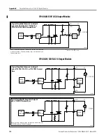
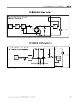
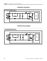
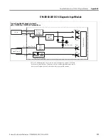
The 1794-IB16D input module provides 16 points of 24V DC sinking input
with open wire and short circuit diagnostic features. Each input signal has an
associated sensor power connection. The module monitors current and voltage at
each input channel sensor power terminal.
Two module indicators and four diagnostic bits report fault conditions:
• the module Fault indicator and the individual faulted channel indicator
also turn red under open and short conditions.
• the module Fault indicator turns red for reverse user power conditions.
• the open bit is set for open sensor and wiring conditions.
• the short bit is set for shorted sensor and wiring conditions.
• the reverse power bit is set for reverse polarity user power conditions.
• the module fault bit is set for any open, short, or reverse power conditions
detected.
Diagnostic Capabilities
The module’s diagnostic capability depends on the connected sensor type.
For 2-wire sensors and contact input devices (for example, switches):
• an open fault will be detected when an open occurs on either the
sensor-power wire, the input signal wire, or the input sensor field device.
• a shorted circuit from a sensor-power wire to common fault (-V) is
detected as a short fault (no voltage at the sensor-power port).
• a shorted circuit from the sensor-power wire to the input-signal wire
cannot be detected. It appears as an on/active input device.
• a shorted circuit from the input-signal wire to common (-V), with the
input sensor field device in the off-state (field device contacts open),
cannot be detected. It appears as an off/inactive input sensor device.
• a shorted circuit from the input-signal wire to common (-V), with the
input sensor field device in the on-state (field device contacts closed), is
detected as a short fault if the sensor field device can pass the sensor power
short circuit current.
• a shorted 2-wire input sensor field device (contact field device) cannot be
detected. It appears as an on/active input field device.
• a shorted circuit from a sensor-power wire, an input sensor wire, or the
input-sensor field device to the DIN rail or chassis ground cannot be
detected.
A dummy resistor must be placed across the contacts of contact input devices (for
example, switches). Use 20 k
resistors.
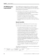
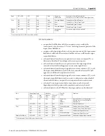
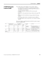
Fault
Device State
Fault Indicators
Error Bit
Status
Conditions
Field Device
Input Status
Module Fault
Channel
Fault

