108
Rockwell Automation Publication 1794-UM061B-EN-P - March 2020
Appendix A
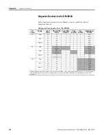
Interpret the Indicators
Diagnostic Functions for the 1794-IB16D
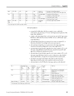
Each unused sensor port requires a dummy resistor to mask the channel
diagnostic function.
Diagnostic Functions for the 1794-IB16D
Ext.
Power
Wiring
Input
Status
Channel LED
Status
Open Wire
Error Bit
Short
Error Bit
Rev.
Error Bit
Module Error
Bit/LED
OFF
Open
Off
Off
0
0
0
0/OFF
On
Off
0
0
0
0/OFF
Short
Off
Off
0
0
0
0/OFF
On
Off
0
0
0
0/OFF
Normal
Off
Off
0
0
0
0/OFF
On
Off
0
0
0
0/OFF
ON
Open
Off
RED
1
0
0
1/RED
On
RED/YEL
1
0
0
1/RED
Short
Off
RED
0
1
0
1/RED
On
RED/YEL
0
1
0
1/RED
Normal
Off
Off
0
0
0
0/OFF
On
YEL
0
0
0
0/OFF
REV
Open
Off
Off
0
0
1
1/RED
On
Off
0
0
1
1/RED
Short
Off
Off
0
0
1
1/RED
On
Off
0
0
1
1/RED
Normal
Off
Off
0
0
1
1/RED
On
Off
0
0
1
1/RED
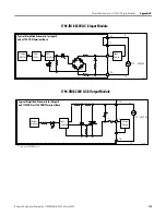
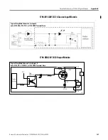
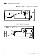
The module monitors each sensor-power port for current and voltage. It turns on the channel red LED and sets (1) the error bit when
1) the module detects a short circuit (no voltage at the sensor-port), and 2) the module detects an open wire (no current at the
sensor-port).


