126
Rockwell Automation Publication 1794-UM061B-EN-P - March 2020
Appendix B
Simplified Schematics of FLEX I/O Digital Modules
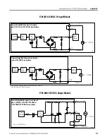
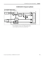
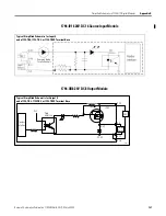
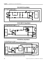
1794-IC 48V DC 16 Input Module
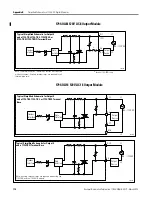
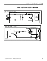
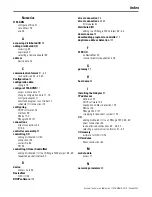
1794-OC 48V DC 16 Output Module
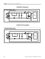
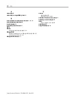
1794-OW8 Relay Output Module
Input
Device
+
-
+48V
COM
A-0
C-35
C-34
B-16
Opto
Isolation
Flexbus
Interface
40107
Typical Simplified Schematic for Input 0
and a 1794-TB3 or 1794-TB3S Terminal Base
40117
Flexbus
Interface
V
CC
Opto
Isolation
Output
Device
+48V
OUT
COM
48V
C-34
A-0
B-17
B-16
+
-
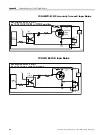
Typical Simplified Schematic for Output 0
and a 1794-TB2, 1794-TB3, or 1794-TB3S Terminal Base
40146
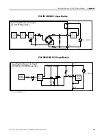
Typical Simplified Schematic for Output 0
and a 1794-TB2, 1794-TB3, 1794-TB3S, or (1794-TBN, 1794-TBNF) Terminal Base
Flexbus
Interface
V
CC
Opto
Isolation
Interface
Circuitry
24V
COM
C-34
A-0 (B-0)
A-1 (C-1)
B-16
Load
Power
+
24V
Note: Auxiliary terminal strips are required for all terminal base units except the 1794-TB3
and 1794-TB3S when load power is 24V DC and channel-to-channel isolation is not needed.
*
Fuse on 1794-TBNF only
*
-


