Rockwell Automation Publication 2198-UM001D-EN-P - May 2014
129
Configure and Start the Kinetix 5500 Drive System
Chapter 6
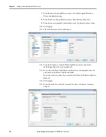
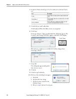
16.
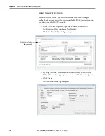
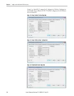
Click the Static Motor Test tab.
17.
Click Start to run the test and measure Motor Stator Resistance.
If you chose the Basic Volts/Hertz category, you can skip this test.
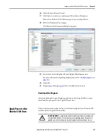
18.
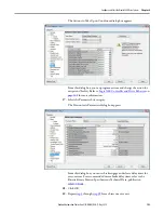
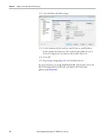
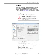
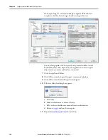
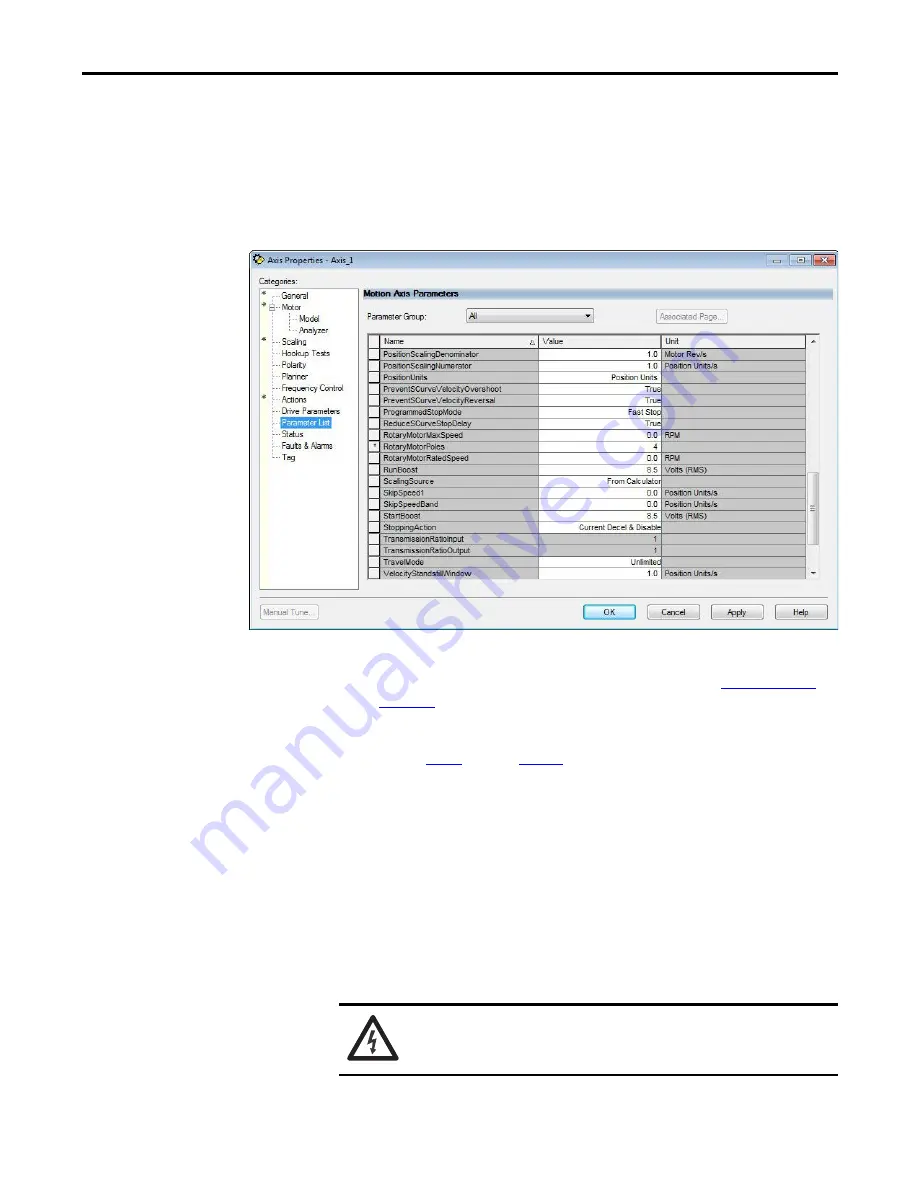
Select the Parameter List category.
The Motion Axis Parameters dialog box appears.
19.
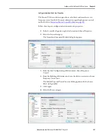
Enter values for the SkipSpeed1 and SkipSpeedBand parameters.
For more information regarding skip frequency, refer to
on
.
20.
Click OK.
21.
Repeat
through
for each induction motor axis.
Download the Program
After completing the Logix Designer application and saving the file you must
download your program to the Logix5000 processor.
Apply Power to the
Kinetix 5500 Drive
This procedure assumes that you have wired and configured your Kinetix 5500
system and your Logix5000 controller.
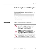
SHOCK HAZARD:
To avoid hazard of electrical shock, perform all mounting and
wiring of the Bulletin 2198 servo drives prior to applying power. Once power is
applied, connector terminals can have voltage present even when not in use.


