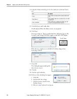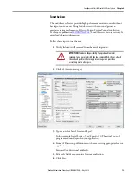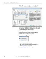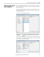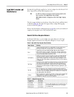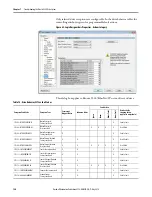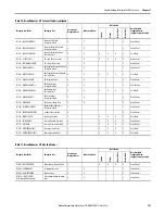
136
Rockwell Automation Publication 2198-UM001D-EN-P - May 2014
Chapter 6
Configure and Start the Kinetix 5500 Drive System
Bus Sharing Group Example
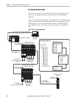
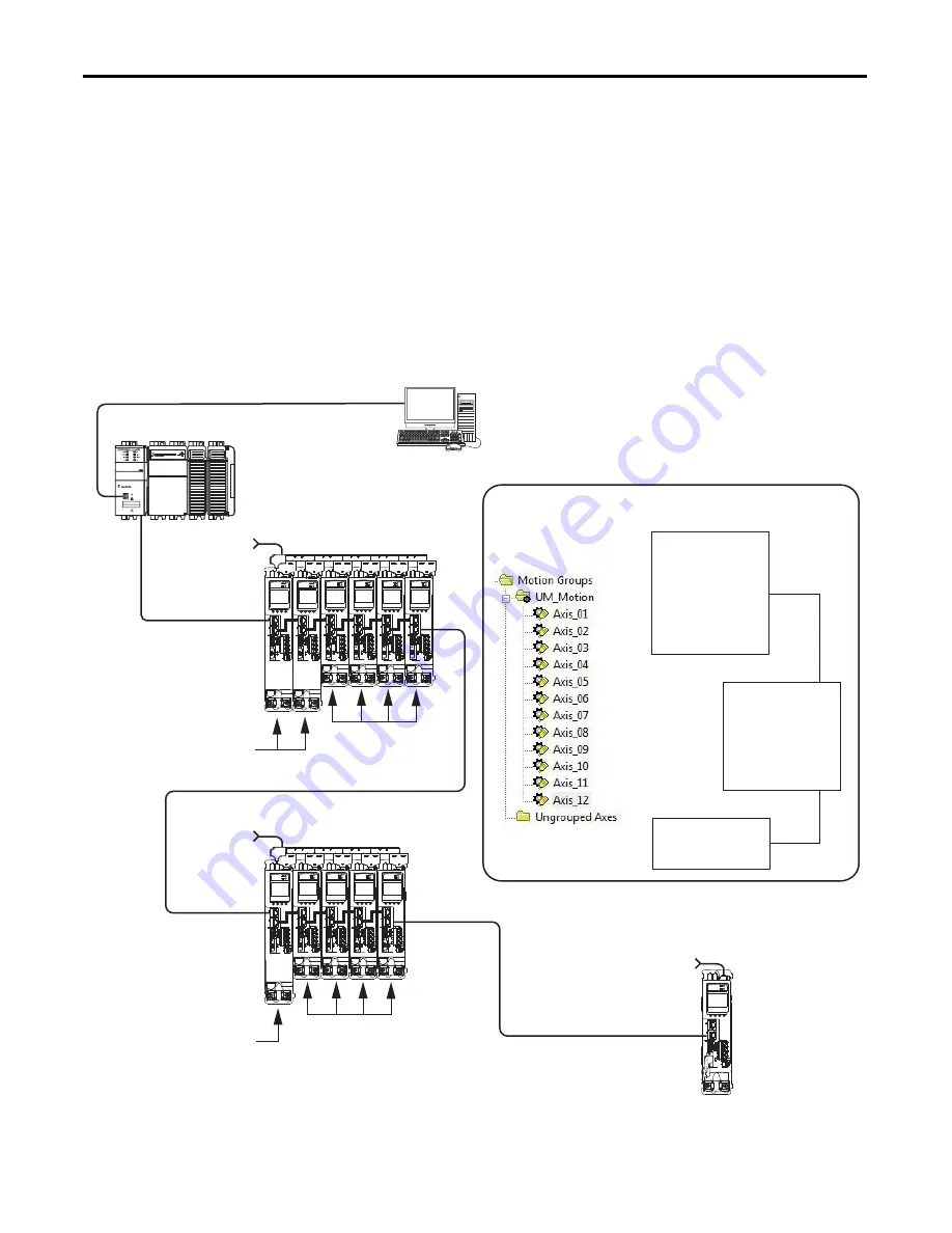
In this example, twelve axes are needed to support the motion application. All
twelve axes are configured in the same Motion group in the Logix Designer
application.
However, the twelve axes of motion are also configured as two bus-sharing groups
and one standalone drive in Module Properties>Power tab. By creating two bus-
sharing groups, a converter drive that faults in Group 1 only disables Group 1
drives, and has no effect on the drive operation of Group 2 or the Standalone
drive.
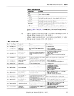
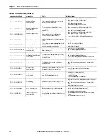
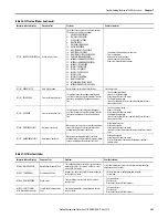
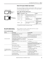
Figure 59 - Bus-sharing Group Example
Kinetix 5500 Servo Drive System
Group 1 (shared AC/DC hybrid)
Kinetix 5500 Servo Drive System
Group 2 (shared-DC commmon-bus)
Kinetix 5500 Servo Drive
Standalone
2198-H040-ERS
x
Common-bus Leader Drive
2198-H003-ERS
x
Common-bus
Follower Drives
2198-H040-ERS
x
Common-bus (converter)
Leader Drives
2198-H003-ERS
x
Common-bus (inverter)
Follower Drives
Three-phase and
24V Input Power
Three-phase and
24V Input Power
Three-phase and
24V Input Power
CompactLogix 5370 Controller
Logix Designer
Application
1585J-M8CBJM-
x
Ethernet (shielded) Cable
CompactLogix Controller Programming Network
Logix Designer Application
Bus Sharing Group 1
Axis_01
Axis_02
Axis_03
Axis_04
Axis_05
Axis_06
Bus Sharing Group 2
Axis_07
Axis_08
Axis_09
Axis_10
Axis_11
Standalone
Axis_12
1585J-M8CBJM-
x
Ethernet (shielded) Cable
Controller Organizer
Module Properties>Power Tab


