130
Rockwell Automation Publication 2198-UM001D-EN-P - May 2014
Chapter 6
Configure and Start the Kinetix 5500 Drive System
Follow these steps to apply power to the Kinetix 5500 system.
1.
Disconnect the load to the motor.
2.
Apply 24V DC control power.
The LCD display begins the startup sequence. Refer to
. If the startup sequence does not begin, check the 24V control
power connections.
3.
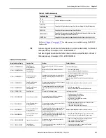
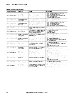
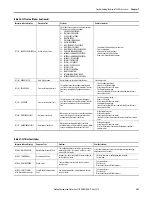
When the startup sequence completes, verify that the two status indicators
are steady green and the axis state is PRECHARGE.
If the axis state does not reach PRECHARGE and the two status
indicators are not solid green, refer to
Kinetix 5500 Drive Status Indicators
on
4.
Apply mains input power and monitor the DC BUS voltage on the LCD
display.
If the DC BUS does not reach the expected voltage level, check the three-
phase input power connections. Also, it can take as many as 1.8 seconds
after input power is applied before the drive can accept motion commands.
5.
Verify that the axis state changes to STOPPED.
If the axis state does not change to STOPPED, refer to
on
Applying Power after Changing Input Voltage Range
This step applies to any drive or multi-axis drive configuration.
ATTENTION:
To avoid personal injury or damage to equipment,
disconnect the load to the motor. Make sure each motor is free of all
linkages when initially applying power to the system.
IMPORTANT
Apply control power before applying three-phase AC power. This
makes sure the shunt is enabled, which can prevent nuisance faults or
Bus Overvoltage faults.
ATTENTION:
To avoid damage to equipment when the configured input
voltage range of the drive or drives changes from 230V AC to 460V AC or from
460V AC to 230V AC, the bus voltage needs to bleed down below 50V DC
before the new configured input voltage is applied.


