200
Rockwell Automation Publication 2198-UM001D-EN-P - May 2014
Appendix A
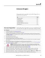
Interconnect Diagrams
System Block Diagrams
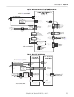
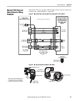
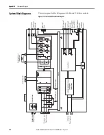
This section provides block diagrams of the Kinetix 5500 drive modules.
Figure 97 - Kinetix 5500 Drive Block Diagram
L1
L2
L3
DC+
DC-
DC+
SH
U
V
W
24V+
24V
-
Th
re
e-ph
ase In
put
Po
w
er C
onnec
tor
DC
B
us C
onn
ec
tor
In
te
rn
al
o
r E
xte
rn
al
Shun
t Re
sit
or
Sh
un
t C
on
nec
to
r
24V C
on
tr
ol
Po
w
er
C
on
ne
ct
or
AC
G
round Jumper
DC
G
rou
nd
Ju
mp
er
Swit
ched
Mode P
ow
er Su
ppl
y
Co
nt
ro
l P
owe
r
Encoder P
ow
er
Co
nt
ro
l B
oa
rd
Ch
as
sis
Th
re
e-
ph
as
e
Mo
to
r P
oewr
Co
nn
ec
to
r
Mo
tor C
abl
e
Cl
am
p
Saf
e T
or
que
-o
ff
Co
nnec
tor
D
igital Inpu
ts
Co
nn
ec
to
r
Et
he
rn
et
P
OR
T1
Et
he
rn
et
P
ORT
2
Mot
or F
eedback
Co
nn
ec
to
r
Mo
tor B
rak
e
Co
nnec
tor
LC
D D
is
pl
ay
Mod
ule Sta
tu
s
Ne
tw
or
k Sta
tus
St
at
us
In
di
ca
tor
s

