background image

Rockwell Automation Publication 2713P-UM001G-EN-P - May 2022

67


Chapter 3

View Information for the 
Configured Controller

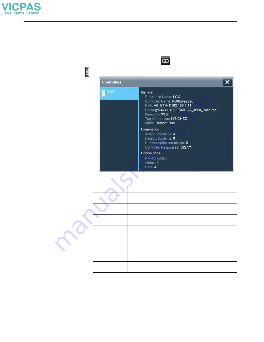
You can view general information for the controller that is configured to operate 
with the terminal.

To view the general information for the controller, follow these steps.

1.

On an application screen, press 

.

2.

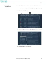
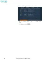
On the Settings screen, tap Controllers.

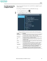
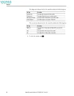
The general information for the controller includes the following data. 

Data Type

Description

Reference Name

The name of the controller reference that is configured in the View Designer application. 

The name does not appear if a controller is not configured for the project. 

Controller Name

The name of the controller that is configured in the Logix Designer application. The name 

does not appear if a controller is not configured for the project.

Path

The communication path for the controller. The path does not appear if a controller is not 

configured for the project.

Catalog

The Catalog number of the controller. The catalog number does not appear if the controller 

is disconnected from the network.

Firmware

The major and minor revision numbers for the firmware in the controller. The firmware 

revision numbers do not appear if the controller is disconnected from the network.

Tag information

The synchronization state to process changes from the controller. For example, the state 

can be Synchronized, Updating, or Detecting changes. Some tag information cannot 

appear if the controller tag information is not synchronized (UNINITIATED).

Mode

The operating mode of the controller. For example, the mode can be Run, Program, or 

Fault. The mode does not appear if the controller is disconnected from the network.

Summary of Contents for Allen-Bradley 2713P-T10CD1

Page 1: ...s 2713P T6CD1 2713P T6CD1 B 2713P T6CD1 K 2713P T7WD1 2713P T7WD1 B 2713P T7WD1 K 2713P T9WD1 2713P T9WD1 B 2713P T9WD1 K 2713P T10CD1 2713P T10CD1 B 2713P T10CD1 K 2713P T12WD1 2713P T12WD1 B 2713P T12WD1 K User Manual Original Instructions ...

Page 2: ...ation Inc with respect to use of information circuits equipment or software described in this manual Reproduction of the contents of this manual in whole or in part without written permission of Rockwell Automation Inc is prohibited Throughout this manual when necessary we use notes to make you aware of safety considerations Labels may also be on or inside the equipment to provide specific precaut...

Page 3: ...tall the PanelView 5310 Terminal Installation Precautions 20 Environment and Enclosure Information 20 Wiring and Safety Guidelines 21 Outdoor Installation Recommendations 21 Mounting Considerations 23 Mounting Clearances 23 Panel Guidelines 24 Panel Cutout Dimensions 24 Terminal Dimensions 25 Prepare for Panel Mounting 26 Mount the Terminal in a Panel 29 Remove and Replace Power Terminal Block 32 ...

Page 4: ... Firmware Revision 61 Display Terminal Diagnostics 62 Enable the VNC Server 63 Load an Application from Removable Media 64 Reboot the Terminal 65 Change the Date and Time 66 View Information for the Configured Controller 67 Manage Certificates 69 Import a Digital Certificate from Removable Media 69 Delete a digital certificate from the HMI Device 70 Chapter4 Monitor and Manage Control System Alarm...

Page 5: ... Status Indicators 98 Troubleshooting Profiles 98 Import a Troubleshooting Profile 99 Export a Troubleshooting Log 101 Terminal Does Not Start Up 103 Terminal Restarts Intermittently 103 Touch Screen Issues 103 Display Issues 104 Ethernet Issues 105 Cannot Download Application to Terminal 105 Performance Is Slow 105 Resistance to Chemicals 106 Clean the Display 106 Remove Paint and Grease 106 Equi...

Page 6: ...6 Rockwell Automation Publication 2713P UM001G EN P May 2022 Table of Contents Notes ...

Page 7: ...using the Studio 5000 Logix Designer application Summary of Changes This manual contains new and updated information as indicated in the following table Package Contents The PanelView 5310 terminals ship with these items IMPORTANT You must configure the Ethernet settings and update the firmware before you can download aView Designer project and use the terminal See Initial Startup on page 37 Topic...

Page 8: ...website http www rockwellautomation com global about us contact contact page Please include Open Source as part of the request text Product Firmware and Release Notes Product firmware and release notes are available online at the Product Compatibility and Download Center at https compatibility rockwellautomation com Pages home aspx 1 On the PCDC home page search for your product 2 On the search re...

Page 9: ... terminal Industrial AutomationWiring and Grounding Guidelines publication 1770 4 1 ProvidesgeneralguidelinesforinstallingaRockwellAutomationindustrial system Guidelines for Handling Lithium Batter iesTechnical Data publication AG 5 4 Provides guidelines to store handle install and dispose of lithium batter ies Safety Guidelines for the Application Installation and Maintenance of solid state Contr...

Page 10: ...10 Rockwell Automation Publication 2713P UM001G EN P May 2022 Preface Notes ...

Page 11: ... applications 1 Connection to one ControlLogix 5570 or 5580 controller or one CompactLogix 5370 5380 or 5480 controller with revision 27 firmware or later Supports a maximum of 100 user defined screens Supports a maximum of 4 000 Logix based alarms 1 Easily configured screen navigation menu Automatic Diagnostics capability Conformal coating available for all terminal sizes Topic Page Topic Page Ab...

Page 12: ...power input 3 Ethernet port One 10 100Base T Auto MDI MDI X EtherNet IP port for controller communication 4 Mounting slots Mounting levers insert into the slots to mount device in a panel or enclosure The number of slots varies by terminal size 5 Universalserialbus USB host port One USB 2 0 high speed type A host port 6 USB device port One USB 2 0 high speed type B device port to connect a host co...

Page 13: ...ove your fingertip over the target on the HMI display without contact loss For a list of actions you can perform by using touch gestures see the View Designer help ATTENTION The touch screen accepts input from a finger stylus or gloved hand for operation in dry or wet environments The plastic stylus must have a minimum tip RADIUS of 1 3 mm 0 051 in Any other object or tool can damage the touch scr...

Page 14: ... and download the project to the terminal You can create an application for any PanelView 5310 terminal and reuse that same application across the entire platform Logix Designer application you can develop control logic for a CompactLogix or ControlLogix controller and download the logic to the controller Figure 1 How Studio 5000 ApplicationsWork Together LINK NET OK 1 2 3 4 5 7 6 8 View Designer ...

Page 15: ...ication uses the tag browser to read data from an ACD file 3 Logix Designer application A Studio 5000 application that is used to develop control logic for an industrial automation system The Studio 5000 Logix Designer application interfaces with controllers to read and write tag information Studio 5000 Logix Designer application projects are stored as ACD files that can be downloaded to the contr...

Page 16: ... the Allen Bradley logo and product identification on the front bezel 3 A catalog number with K at its end for example 2713P T6CD1 K is a terminal with conformal coating Cat No Display Input Power Ethernet Port Memory Touch Screen Display Size Type Aspect Ratio Pixels W x H RAM User 1 2713P T6CD1 2713P T6CD1 B 2713P T6CD1 K 5 7 in VGA TFT color 4 3 640 x 480 DC One 1 GB 1 GB 2713P T7WD1 2713P T7WD...

Page 17: ...1P RMCP 1 Mounting levers black 16 1 Use catalog number 2711P RMCP mounting levers black for PanelView 5310 terminals Do not use gray mounting levers they are not compatible with PanelView 5310 terminals Table 5 Secure Digital SD Cards 1 Cat No Description Quantity 1784 SDHC8 8 GB SDHC card 1 1784 SDHC32 32 GB SDHC card 1 1 To help reduce the chance of corruption when you use SD Cards or USB drive...

Page 18: ...18 Rockwell Automation Publication 2713P UM001G EN P May 2022 Chapter 1 Notes ...

Page 19: ... Dimensions 24 Terminal Dimensions 25 Prepare for Panel Mounting 26 Mount theTerminal in a Panel 29 Remove and Replace PowerTerminal Block 32 Connect Power 33 Connect to a Network 34 Initial Startup 37 ATTENTION Do not use a PanelView 5310 terminal for emergency stops or other controls critical to the safety ofpersonnel or equipment Use separate hard wired operator interface devices that do not de...

Page 20: ...e equipment Sellers or users are required to take caution in this regard 이 기기는 업무용 A 급 전자파적합기기로서 판 매자 또 는 사용자는 이 점을 주의하시기 바 라 며 가정외의 지역 에서 사용하는 것을 목적으 로 합니다 Thisequipmentissuppliedasopen typeequipment Itmustbemountedwithinan enclosure that is suitably designed for those specific environmental conditions that can be present and appropriately designed to help prevent personal injury resulting from a...

Page 21: ... the display the temperature between the sun shield and the display cannot exceed the maximum temperature of the display which is 50 C 122 F Adequately ventilate all sun shields to help prevent excess heat rise on the terminal display ATTENTION Use publication NFPA 70E Electrical Safety Requirements for EmployeeWorkplaces IEC 60364 Electrical Installations in Buildings or other applicable wiring s...

Page 22: ...to solar heating during the hottest part of the day Mount the terminal vertically to minimize solar heating on the display Do not mount the terminal in a sloped enclosure if it exposes the terminal to direct sunlight For more information see Mounting Considerations on page 23 To help protect the terminal from water and dust mount it in a proper enclosure by following the instructions in the PanelV...

Page 23: ...nal where it is exposed to direct sunlight Figure 2 Acceptable and Unacceptable Mounting Positions Mounting Clearances Plan for adequate space around the terminal inside the enclosure for ventilation and cables Consider the heat from other devices in the enclosure The ambient temperature around the terminal must be 0 50 C 32 122 F Yes 90 FromVertical 90 FromVertical No Table 8 Minimum Required Cle...

Page 24: ...panel must be sufficient to hold the terminal and maintain an appropriate seal against water and dust The panel surface must be flat and free of imperfections to maintain an adequate seal and NEMA UL Type or IP ratings Panel Cutout Dimensions Use the template that is shipped with your terminal to mark the cutout dimensions PanelView 5310 Panel Cutout Dimensions Terminal Size in InputType Height mm...

Page 25: ...wide terminal shown Table 9 PanelView 5310Terminal Dimensions Display Size in Input Type Height A mm in Width B mm in Overall Depth C mm in Mounted Depth D mm in 6 Touch 153 6 186 7 3 69 5 2 74 64 2 5 1 1 When mounted in a panel the front of the bezel extends less than 6 mm 0 24 in from the panel 7 178 7 237 9 3 9 190 7 5 280 11 10 4 252 9 92 297 11 69 12 1 246 9 7 340 13 4 B A C D ...

Page 26: ...nserting it into a slot This method is the only way to slide the mounting lever knob within the slot for positioning After sliding the mounting lever to a specific notch rotate the mounting lever toward the panel to lock it in position The flat side of the mounting lever must come into contact with the panel IMPORTANT Use catalog number 2711P RMCP mounting levers black for PanelView 5310 terminals...

Page 27: ... orientations for all terminals Figure 4 Mounting Levers Shown in Locked Position Flat Side Knob on reverse side of lever inserts into large end of slot 1 2 3 4 You can use an erasable marker or grease pencil to mark the indentations for visibility of slot positions Innernotch on lever showscurrent leverposition Inner Notch Outer Notch The edge of the bezel has alignment indentations to assist wit...

Page 28: ... Touch Widescreen 10 Levers 1 6 in Touch Screen 4 Levers 3 2 4 1 3 4 2 5 6 3 1 2 4 8 6 5 7 3 1 2 4 6 7 8 5 10 9 IMPORTANT ThemountingleverorientationsthatareshownarerequiredtomaintainNEMA ULType andIP seals If you require a NEMA ULType or IP seal do not use a mounting lever in another orientation than shown Flat Side Round Side Flat Side Round Side 10 4 in Touch Screen 8 Levers 3 1 2 4 8 6 5 7 ...

Page 29: ...t levers in the top corner slots in the orientation that is shown and rotate the non flat side of the levers toward panel ATTENTION Disconnect all electrical power from the panel before making the panel cutout Makesure thattheareaaroundthepanelcutoutisclearandthatthepanelisclean of any debris oil or other chemicals Make sure that metal cuttings do not enter any components that are already installe...

Page 30: ...erminal The direction that you rotate the levers varies for each terminal size 4 Slide and rotate each lever to a notch that is one or two positions greater than the final lock position Start with the first lever in the sequence For example if the final lock position is 3 slide the lever to notch 4 or 5 a See Table 10 on page 26 to get the final lock position of the levers b See Figure 5 on page 2...

Page 31: ...ith the bezel indentation c Carefully rotate the lever back toward panel d Lock the remaining levers to their final position 6 Inspect all levers and make sure each is in the correct locked position The notch on the outside of lever shows its locked position These two views show levers that are locked in position 4 TIP A broken lever does not damage the product ATTENTION All levers must be in the ...

Page 32: ...m terminal To install the power terminal block follow these steps 1 Press the terminal block base in first with the terminal block leaning outward 2 Gently push the top of the terminal block back to vertical position to snap in the locking tab SHOCK HAZARD Turn off the power before you connect or disconnect wiring If the power is on an electric arc can occur Failure to turn power off can result in...

Page 33: ...3 Secure the DC power wires to the marked terminals and on the terminal block Table 12 DC Power Ratings Terminal Power Supply InputVoltage Power Consumption 2713P T6CD1 Non isolated 24V DC nom 18 30V DC 13W max 0 54 A at 24V DC 2713P T7WD1 2713P T9WD1 14W max 0 58 A at 24V DC 2713P T10CD1 15W max 0 62 A at 24V DC 2713P T12WD1 16W max 0 67 A at 24V DC ATTENTION The power supply is internally protec...

Page 34: ...th RJ45 connectors ATTENTION The FEground connection to FEgroundismandatory This connection is required for noise immunity reliability and Electromagnetic Compliance EMC with the European Union EU EMC Directive for CE marking conformance This connection is required for safety by Underwriters Laboratory UL IMPORTANT Secure the power cable to help prevent these actions Vibration at the connector Pul...

Page 35: ...ceoranydeviceonthenetwork Ifthepoweris on an electric arc can occur Failure to turn power off can result in electric shock or damage to the terminal Table 13 Ethernet Connector Pinout Connector Pin Pin Name View of RJ45 Connector 1 TD 2 TD 3 RD 4 Unused 5 Unused 6 RD 7 Unused 8 Unused Shield connection No direct connection AC coupled to chassis GND Table 14 Ethernet Status Indicators Indicator Col...

Page 36: ...logy is a traditional EtherNet IP network that has multiple devices that are connected to each other via an Ethernet switch Figure 7 PanelView 5310Terminal Connected Via a Stratix 6000 Switch PanelView 5310Terminal Kinetix 350 Drive Connected Via a 1783 ETAP EtherNet IPTap Kinetix 350 Drive Connected Via a 1783 ETAP EtherNet IPTap 1769 L27ERM QBFC1B Control System 1794 AENTR FLEX I O Adapter with ...

Page 37: ...the Terminal When power is turned on the terminal goes through its startup sequence The Welcome screen displays with a Configure the Ethernet Network button To configure the Ethernet settings and update the firmware follow these steps 1 Start up the terminal The Welcome dialog box displays IMPORTANT YoumustconfiguretheEthernetsettingsandupdatethefirmwarebeforeyou can download aView Designer projec...

Page 38: ...48 To configure IP settings manually see Assign a Static IP Address for the Terminal on page 49 4 Tap the Ethernet icon 5 Configure the Ethernet ports for the terminal See Configure the Ethernet Port on page 51 6 Update the firmware by using the ControlFLASH or ControlFLASH Plus software Begin the update at Get the Terminal Firmware on page 93 You can now download a View Designer application to th...

Page 39: ...rt Display error information Configure terminal settings and view diagnostic information Topic Page Topic Page Runtime Environment 39 Calibrate theTouch Screen 57 Enter DataWithVirtual Keyboards 41 Disable Downloads to theTerminal 59 Log On to theTerminal 44 Change the HMI Device Name 60 Log Off of theTerminal 45 View the Firmware Revision 61 Settings Menu 45 DisplayTerminal Diagnostics 62 Configu...

Page 40: ...ollecting data or exporting The media containing the data log is ready to remove without corrupting files or making files read only on the USB storage device or SD card Tags in the data log are in error You can select the icon toview the error details A data log status icon only appears when a project contains a data log and there are no project event errors Project events and data logs are in err...

Page 41: ...eld 3 Backspace Tap this key to delete one character to the left at a time 4 éüç Tap this key to toggle between Roman characters and alpha European characters Numeric keys are not part of the alpha European keyboard 5 Arrow keys Taptheleftarrowkeytomovethecursoronespacetotheleft Taptherightarrowkey to move the cursor one space to the right 6 Cancel Tap Cancel to cancel the entry 7 OK Tap OK to com...

Page 42: ... 16 Virtual Numeric Keypad Description Item Feature Description 1 Numeric entry field The numeric entry field intowhich you type the numeric value for the graphic element 2 Min Max value The displayed minimum and maximum values you can enter for the selected field or element 3 Clear Tap the X to remove all numbers that are entered into the numeric entry field 4 Backspace Tap the backspace button t...

Page 43: ...elect either Normal or Large Figure 10 provides a comparison between the Normal and Large size keypad The larger size of both the keypad and keyboard gives you easier touch operation which is useful if you use gloves during equipment operation Figure 10 Normal versus Large Keypad Normal Size Keypad Large Size Keypad ...

Page 44: ... OK 5 Tap the Password field The virtual keyboard opens 6 To enter your password with no spaces tap the keys Passwords are case sensitive 7 Tap OK 8 Tap Log on The Log On dialog box closes and your user name appears on the Log On button on the status banner TIP TheGuestuserisloggedonautomaticallyatsystemstartup Anyonethatis notloggedontothesystemcanvieworaccessonlythosescreensassigned the level of...

Page 45: ... user does not have access to the current screen the Home screen for the project is displayed To log off the terminal follow these steps 1 In the status banner at the top of the screen tap that shows your user name The Log On dialog box opens 2 Tap Log Off You are logged off the terminal Settings Menu You can access configuration parameters and systemwide information for the terminal from the Navi...

Page 46: ...twork Configure a static or dynamic device IP address Configure Ethernet Link 1 settings View network diagnostics 2 Display Adjust the brightness of the display Enable or disable the screen saver Configure the screen saver settings Calibrate the touch screen 3 HMI Device Enable or disable downloads and firmware updates Enter an HMI device name View the catalog number and current firmware revision ...

Page 47: ...upport 6 Date andTime Set the date and time on the terminal Set the time zone on the terminal 7 Controllers View general information for the controller View diagnostic information for the controller 8 Load from Media Load an application to the HMI device from removable media 9 VNC Configure theVNC server and view the connection status 10 Email Configure the terminal to send and receive email 11 Ce...

Page 48: ...he View Designer software through the IP address of the terminal Use DHCP to Assign an IP Address for theTerminal In a DHCP configuration the network assigns the IP address subnet mask and default gateway address fields To configure DHCP for the terminal follow these steps 1 On an application screen press 2 On the Settings screen tap 3 Tap the Obtain IP settings automatically using DHCP radio butt...

Page 49: ...n the IP Settings Configuration 4 Tap the IP address field The virtual keyboard opens 5 To enter the IP address use the virtual keyboard 6 Tap OK to close the virtual keyboard 7 Repeat steps 4 6 for the subnet mask and the Gateway address fields 8 To close the window tap Parameter Description IP address The range of values for the first set of numbers is 1 255 The range of values for last three se...

Page 50: ...ication screen press 2 On the Settings screen tap 3 Tap the Manually configure IP settings radio button Follow these guidelines to assign the DNS settings 4 Tap the Primary DNS field The virtual keyboard opens 5 To enter the DNS address use the virtual keyboard 6 Tap OK to close the virtual keyboard 7 Repeat steps 4 6 for the Secondary DNS and the Tertiary DNS fields 8 To close the window tap TIP ...

Page 51: ...ct the Ethernet options for your network configuration Tap the Enable Ethernet Link 1 checkbox to add or remove the check mark The option is enabled when the box is checked To set the speed and duplex options that are based on the network connection tap the Auto negotiate checkbox The option is enabled when the box is checked To set the speed and duplex options tap the Auto negotiate checkbox to r...

Page 52: ...etwork Diagnostics screen you can view Ethernet Link 1 network connection data network status data and IP settings configuration data To view the Network Diagnostics screen follow these steps 1 On an application screen press 2 On the Settings screen tap 3 Tap the network diagnostic icon 4 To close the window tap ...

Page 53: ...tion screen press 2 On the Settings screen tap 3 In the Export to file box type a name for the export file Datalog is the default name 4 Under Destination select the media type 5 Tap Export A progress bar appears to show export progress and a data log popup displays the date and time of the last exported data log 6 If an SD card is used verify the following before you remove the media a After the ...

Page 54: ...y follow these steps 1 On an application screen press 2 On the Settings screen tap 3 Tap the Brightness field The virtual numeric keypad opens 4 Enter the value for the brightness in increments from 1 100 5 Tap OK 6 To close the window tap TIP Lower the brightness level to reduce the power that the backlight consumes and extend the life of the backlight These tags can also be set to control backli...

Page 55: ...r or lower values using your Numeric Inputs Configure the Display Screen Saver The screen saver extends the life of the back light by dimming the brightness level when activity is not sensed for a specified amount of time When the screen saver is activated the terminal displays a moving image at a reduced brightness level When user input is sensed the screen saver is deactivated and the display br...

Page 56: ...when the box is checked 4 Tap the Wait field The virtual numeric keyboard opens 5 Enter the number of continuous idle minutes from 1 5999 to wait before activating the screen saver The default is 10 minutes 6 Tap OK 7 Tap the Brightness field The virtual numeric keyboard opens 8 Enter the value for the brightness in increments from 1 100 9 Tap OK 10 To close the window tap ...

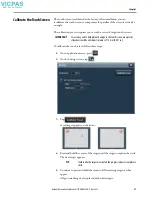
Page 57: ...follow these steps 1 On an application screen press 2 On the Settings screen tap 3 Tap A red target appears on the screen 4 Press and hold the center of the target until the target completes the circle The next target appears 5 Continue to press and hold the centers of all remaining targets as they appear All processed targets are replaced with white targets IMPORTANT For accuracy and to help prev...

Page 58: ...ndicates a successful calibration A red circle with an X indicates a failed calibration If the calibration fails the process automatically repeats Continue the calibration until the calibration is successful 6 Tap OK 7 To close the window tap TIP The calibration is retained after a reset or power cycle ...

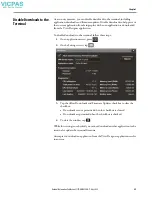
Page 59: ...er application To disable downloads to the terminal follow these steps 1 On an application screen press 2 On the Settings screen tap 3 Tap the Allow Downloads and Firmware Updates checkbox to clear the checkbox Downloads are not permitted when the checkbox is cleared Downloads are permitted when the checkbox is checked 4 To close the window tap While this setting is unchecked you cannot download a...

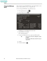
Page 60: ...I device name follow these steps 1 On an application screen press 2 On the Settings screen tap The HMI device name field shows the current name 3 Tap the HMI device name field The virtual keyboard opens 4 To enter or modify the current name tap the virtual keyboard keys 5 Tap OK 6 To close the window tap TIP You can enter up to 15 characters including letters numbers and hyphens The first characte...

Page 61: ...e current firmware revision on the terminal You need this information for firmware updates or when you call technical support To view the firmware revision follow these steps 1 On an application screen press 2 On the Settings screen tap View the firmware revision under Product Information 3 To close the window tap ...

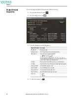
Page 62: ...of the CPU Normal 25 94 C 77 201 F High 100 C 212 F and higher An over temperature condition of 105 110 C 221 230 F causes a delayed automatic system restart The restarts continue indefinitely until the system is cool enough to resume normal operation Last reboot Displays the dateand time forthe most recent restart of the terminal Last deploy Displays the date and time of the most recent project a...

Page 63: ... or disable a VNC connection follow these steps 1 On an application screen press 2 On the Settings screen tap 3 Select an access Disabled Disables the VNC server Enabled with view only access You can only view content on the HMI device Enabled with full control access You can view content and interact with the HMI device 4 To close the window tap TIP A warning displays with full control access tha...

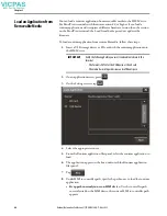
Page 64: ...with the runtime application into the HMI device 2 On an application screen press 3 On the Settings screen tap 4 Select the appropriate source 5 From the Runtime application files panel select the runtime application to load 6 The application appears in the box underneath the Runtime application files panel 7 Tap 8 Under HMI to controller path specify the path to use to load the runtime applicatio...

Page 65: ...y a part of the Studio 5000 install located at C Users Public Documents Rockwell Automation Firmware Kits 9 Tap Load The HMI device performs a firmware update if needed and then loads and runs the runtime application The Home screen of the runtime application opens on the HMI device 10 To close the window without performing the load from media tap Reboot theTerminal To restart the terminal follow ...

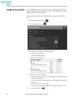
Page 66: ... appropriate a Tap a Date or Time field The virtual keyboard opens b Enter a value and tap OK 4 Change the time zone if desired a To move up and down the list press and drag the scroll bar or press and hold an arrow button Or tab to the list and use the arrows keys on the physical keypad of the terminal b Tap the time zone for the terminal The time on the terminal is adjusted to match the selected...

Page 67: ...plication The name does not appear if a controller is not configured for the project Path The communication path for the controller The path does not appear if a controller is not configured for the project Catalog TheCatalognumberofthecontroller Thecatalognumberdoesnotappearifthecontroller is disconnected from the network Firmware The major and minor revision numbers for the firmware in the contr...

Page 68: ...items on scan for the controller Failed data items The number of failed data items on scan for the controller Number optimized blocks The numeric of optimized data blocks on scan for the controller Controller Responses The number of responses received from the controller Data Type Description HMIBC I O The number of Class 1 Common Industrial Protocol CIP connections to the controller Alarm The num...

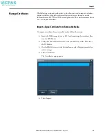
Page 69: ...ertificates must have a cer crt or pem extension Import a Digital Certificate from Removable Media To import a certificate from removable media follow these steps 1 Insert the USB storage device or SD Card containing the certificate files into the HMI device 2 Verify that the certificate files are in the root directory of the SD card or the USB drive 3 On the HMI device or in the System Banner sel...

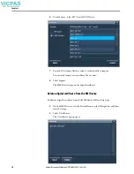
Page 70: ... import You can only import one certificate file at a time 8 Select Import The HMI device imports the digital certificate Delete a digital certificate from the HMI Device To delete a digital certificate from the HMI device follow these steps 1 On the HMI device or in the System Banner select Navigation and then select Settings 2 Select Certificates The Certificates popup opens ...

Page 71: ...tomation Publication 2713P UM001G EN P May 2022 71 Chapter 3 3 From the certificates list select the certificate file to delete You can only select one certificate file at a time 4 Select Delete and then select OK ...

Page 72: ...72 Rockwell Automation Publication 2713P UM001G EN P May 2022 Chapter 3 Notes ...

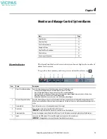
Page 73: ...unacknowledged alarms and indicates all alarms have returned to normal but some alarms are still unacknowledged A red button indicates there are active alarms and all of them are acknowledged 2 Automatic Diagnostics button Opens the Automatic Diagnostics screen which automatically shows control system faults with no HMI configuration work The button shows a notification with the number of active d...

Page 74: ...k status Appears only if there is an issue with network communication Tap the icon to open the Device Configuration Network popup for details about the issue One of the following messages may appear Networkcaution thenetworkisfunctioningbuthasanissuethatrequiresattention Forexample theDeviceLevelRingmay have a break Network error the network is not functioning For example an Ethernet link is disco...

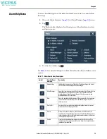
Page 75: ...nagerlistsallalarmsthatare configured in the system and their current states Therefore the alarm manager shows alarms that are not shown in the alarm summary and provides additional tasks for alarms Back Opens the previously displayed screen When you open the alarm manager screen from the alarm summary screen this button reopens the alarm summary screen Deselect All Deselects all alarms in the ala...

Page 76: ...l conditions of the currently selected alarm Reset Latched Sets the selected digital latched state of the alarm to normal if the input of the alarm has returned to normal A reset of a digital latched alarm acknowledges the alarm if it is not acknowledged Select All Selects all alarms in the alarm table including the alarms that are not displayed on the current page of alarms Select Page Selects al...

Page 77: ...o monitor and interact with alarms To view the alarm summary for the control system follow these steps 1 On an application screen press 2 Tap or tab to the menu item and press Enter 3 To interact with the alarms tap the alarm function keys See Alarm Help Menu on page 75 for a description of the keys 4 To return to the navigation menu tap the navigation button on an application screen 5 To return t...

Page 78: ...s To manage the alarms for the control system follow these steps 1 On an application screen press 2 Tap or tab to the menu item and press Enter 3 To manage the alarms tap the alarm function keys See Alarm Help Menu on page 75 for a description of the keys 4 To return to the navigation menu tap on an application screen 5 To return to the application screens tap an application icon ...

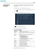
Page 79: ...rm Class The user defined class that is assigned to the alarm in the Studio 5000 Logix Designer project Alarm Count The number of times the alarm condition has entered the In Alarm state Alarm State The state of the alarm condition Normal Unacknowledged Normal Unacked In Alarm Acknowledged In Alarm Acked In Alarm Unacknowledged In Alarm Unacked Normal Acknowledged Acknowledge Condition Analog cond...

Page 80: ...he selected alarm entered the Normal or Inactive state Priority The urgency of the alarmcondition Low Medium High Urgent Quality The list of reasons why the alarm is of bad quality This field is blank in the alarm summary because the alarm summary does not show bad quality alarms Severity The numeric value that is mapped to the assigned priority of the alarm condition 1 250 low 251 500 medium 501 ...

Page 81: ...rms in the selected alarm state To filter the alarms follow these steps 1 To the right of the filter field tap 2 To scroll through the filter choices tap the up or down arrows on the scroll bar 3 Tap the alarm filter that you want to use TIP Filters are defined for the alarm summary alarm manager and alarm history viewer inView Designer ...

Page 82: ...mation Publication 2713P UM001G EN P May 2022 Chapter 4 The selected filter displays in the filter pull down menu To change the filter tap the filter pull down menu and select another filter To turn off the filter tap ...

Page 83: ...ss Enter The Alarm History Viewer displays the alarm history 3 To change the way information is presented you can sort columns by clicking on the column header or select filters by following the instructions in Filter the Alarms on page 81 Export the Alarm History You can export the alarm history to an SD card or USB drive The alarm history is exported as a zipped CSV file that can be opened and a...

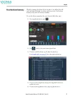
Page 84: ...ostics for your controllers This capability is available for ControlLogix 5580 and CompactLogix 5380 5480 controllers version 33 and later and it automatically displays control system faults with no HMI configuration required on your part To view automatic diagnostics press the automatic diagnostics icon in the system banner A diagnostics summary displays current diagnostic notifications You can s...

Page 85: ...Italian German Spanish Chinese Japanese Korean The history element shows the past 1000 diagnostic events These events are maintained through power cycles and project downloads and they can be cleared by a firmware update or with a Clear Automatic Diagnostics History command ...

Page 86: ...86 Rockwell Automation Publication 2713P UM001G EN P May 2022 Chapter 4 Notes ...

Page 87: ...omponents for future reference Voltage Precautions The terminals contain line voltages Disconnect all power to the terminal before you install or remove components Topic Page Accessories and Replacement Parts 87 Voltage Precautions 87 Electrostatic Discharge Precautions 88 Connect to USB Ports 88 Insert an SD Card 89 Replace the Battery 90 IMPORTANT We recommend that you use only Allen Bradley app...

Page 88: ...s 0 5 A at 5V DC Connected USB devices must not exceed this power load ATTENTION Electrostatic discharge ESD can damage static sensitive devices or microcircuitry Disconnect all power before you work on the terminal as detailed in Voltage Precautions on page 87 Observe proper packaging and grounding techniques to help prevent damage IMPORTANT The USB host connection is intended for temporary use w...

Page 89: ...nel when the operator terminal is installed Follow these steps to install an SD card in the card slot 1 Verify that the SD card is locked or unlocked according to your preference If unlocked the terminal can write data to or read data from the card If locked the terminal can only read data from the card ATTENTION USBdevicesthatare notpowered bytheUSB portmust adhere to the following The USB device...

Page 90: ...a sealed lithium battery which may need to be replaced during the life of the product At the end of its life the battery contained in this product should be collected separately from any unsorted municipal waste The collection and recycling of batteries helps protect the environment and contributes to the conservation of natural resources as valuable materials are recovered WARNING There is a dang...

Page 91: ...l 2 Remove the screws from the logic module 3 Carefully lift the logic module away from the display module and turn over to expose the circuit board 4 Locate the coin cell battery on the circuit board 5 Remove the battery by lifting the side of the battery 6 Insert the new battery so the positive polarity faces up Logic Module Display Module Battery ...

Page 92: ...h the logic module by aligning the connector on the bottom of the logic module with the connector on the display module 8 Push down on the logic module and make sure that it is fully seated 9 Torque the screws to 0 68 0 90 N m 6 8 lb in Module Connectors Logic Module Display Module ...

Page 93: ...ber and current firmware revision Verify that you have a View Designer vpd file of your application currently running on the PanelView 5000 terminal If not upload the application to View Designer so you can re download it after the firmware update The firmware update clears the existing application on the PanelView 5000 terminal but maintains configuration data such as Ethernet settings display br...

Page 94: ... Plus Quick Start Guide publication CFP QS001 Update the Firmware by Using ControlFLASH Plus Software To use the ControlFLASH Plus software to update the firmware in a PanelView 5310 terminal follow these steps 1 Click Start FLASH Programming Tools ControlFLASH Plus 2 To open the FactoryTalk Linx Network Browser click the Network Browse button 3 Select your PanelView 5000 terminal and click OK 4 S...

Page 95: ...m the flash update by pressing Flash 6 Once the flash update is complete press Close 7 To exit ControlFLASH Plus press Done Verify the Firmware Update To verify that the firmware revision is updated use the HMI Device settings For instructions on how to do this see View the Firmware Revision on page 61 ...

Page 96: ...96 Rockwell Automation Publication 2713P UM001G EN P May 2022 Chapter 6 Notes ...

Page 97: ... Profiles 98 Terminal Does Not Start Up 103 Terminal Restarts Intermittently 103 Touch Screen Issues 103 Display Issues 104 Ethernet Issues 105 Cannot Download Application toTerminal 105 Performance Is Slow 105 Resistance to Chemicals 106 Clean the Display 106 Ship theTerminal 107 Restore Factory Defaults 107 Dispose of theTerminal 108 ...

Page 98: ...ormat This profile is stored on the terminal and can be used to improve usability and assist with troubleshooting If you contact technical support a representative can ask you to export the troubleshooting log to a USB drive or SD or SDHC card You can also import a troubleshooting profile from a USB drive or SD card to capture additional data Table 20 Fault Indicator States duringTerminal during S...

Page 99: ...button To import a troubleshooting profile from a USB drive or SD card follow these steps 1 Press the navigation button on an application screen 2 On the Settings screen tap Troubleshooting 3 Insert a USB drive or SD card that contains the troubleshooting profile into the appropriate slot on the terminal 4 Tap Import Profile 5 Tap to select the target USB device or SD card that contains the profil...

Page 100: ...100 Rockwell Automation Publication 2713P UM001G EN P May 2022 Chapter 7 7 To close the window tap OK ...

Page 101: ...Troubleshooting Log To export the troubleshooting log to a USB device or SD card follow these steps 1 Press the navigation button on an application screen 2 On the Settings screen tap Troubleshooting 3 Insert a USB drive or SD card into a slot on the terminal 4 Tap Export The troubleshooting log is exported and the date a time of the last export is displayed next to the Export button ATTENTION Do ...

Page 102: ...close the window tap Your technical support contact at Rockwell Automation can provide you with information on where to send the profile ATTENTION Do not remove the USB drive or SD card before the import operation is complete Otherwise the USB drive or SD card can become corrupt ...

Page 103: ...y during startup Table 22 Terminal Restarts Intermittently Check For What to Do See Improper power wiring Verify that the power wiring is correct Check the wiring specifications Check the DC power wiring page 32 page 33 Over temperature conditions Make sure that the processor is not exceeding temperatures for normal terminal operations Check the processor temperature Check for adequate clearances ...

Page 104: ...hould follow all applicable code and good engineering practice Factors to consider include The possibility of an unreadable display The possibility of an inoperable touch screen Unexpected communication errors or delays Operator error in the control of the system Proper use of E stops and other safety practices The user shall provide means to achieve a safe state during anomalies and make sure the...

Page 105: ...alid IP address of terminal If DHCP is enabled the terminalautomaticallyacquires avalid IP address fromthenetworkafterstartup TheTCP IPprotocolautomaticallyassigns 169 254 xxx xxxwhen it fails to acquire an IP address from the network In general an IP address that begins with 169 does not support a network connection See Configure the IP Address of theTerminal on page 48 Conflict Between IP addres...

Page 106: ...ated enclosure follow these steps 1 Rub lightly with isopropyl alcohol 70 concentration 2 To remove residue use a mild soap or detergent solution 3 Rinse with clean water TIP For more information on chemical resistance of the product go to https rockwellautomation custhelp com and search the Knowledgebase for keywords Chemical Resistance PanelView Plus IMPORTANT Do not operate the terminal in dire...

Page 107: ... pressurewasherforcleaningventedenclosures Watercan enter the enclosure and damage the terminal and other equipment ATTENTION Rockwell Automation is not responsible for damage to a product that is shipped or transported while installed in a panel or enclosure ATTENTION Theprocessthatrestoresfactorydefaultsalsoremovessomedata Upload the application with theView Designer application Record the termi...

Page 108: ...en the restore is complete the terminal performs a normal startup 5 From the Settings menu update the terminal network settings 6 Download an application to the terminal by using the View Designer application 7 From the Settings menu update any remaining terminal settings as appropriate Refer to Disable Downloads to the Terminal on page 59 for details on how to modify device configuration settings...

Page 109: ...e and time setting 66 DC power bus 33 device name 60 DHCP 48 diagnostics data 62 network 52 dimensions product 25 disable downloads to the terminal 59 display brightness 54 unreadable or dimming 104 DNS address primary 50 secondary 50 tertiary 50 E earth ground connection 34 wire 34 environment and enclosure specifications 20 21 equipment wash downs 107 Ethernet connector pinout 35 status indicato...

Page 110: ...s 32 power supply PELV 33 SELV 33 product compatibility and download center 8 product dimensions 25 publications download 9 R reboot the terminal 65 release notes 8 restore factory defaults 107 RJ45 connector 35 runtime 15 39 S safety notices battery replacement 90 earth ground connection 34 electrical arc 32 35 mounting the terminal 29 unintended operation 13 water or chemical damage 29 screen sa...

Page 111: ...Rockwell Automation Publication 2713P UM001G EN P May 2022 111 Index W wash downs 107 wiring and safety guidelines 21 ...

Page 112: ...112 Rockwell Automation Publication 2713P UM001G EN P May 2022 Index Notes ...

Page 113: ...Rockwell Automation Publication 2713P UM001G EN P May 2022 113 User Manual ...

Page 114: ... Locate the telephone number for your country rok auto phonesupport Literature Library Find installation instructions manuals brochures and technical data publications rok auto literature Product Compatibility and Download Center PCDC Download firmware associated files such as AOP EDS and DTM and access product release notes rok auto pcdc At the end of life this equipment should be collected separ...

Reviews: