Publication 900-UM007D-EN-E - January 2011
3-48
Configuration & Basic Operation
•
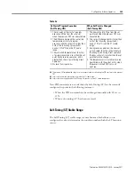
Turn the heater power ON simultaneously or before turning power ON
to the 900-TC8 or 900-TC16 controller. If the heater power is turned
ON after turning ON the 900-TC8 and 900-TC16 power, the HBA will
be activated.
•
The temperature controller continues to attempt to control the system
even when the HBA or HS alarm is active.
•
The displayed current value may sometimes differ slightly from the
actual current flowing to the heater.
Use the Heater Current 1 Value Monitor, Heater Current 2 Value
Monitor, Leakage Current 1 Monitor, and Leakage Current 2 Monitor
parameters to check the actual current being used by the controller for
alarm purposes.
•
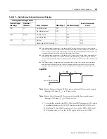
If there is little difference between the displayed current in normal and
abnormal (i.e., alarm) states, detection may become unstable. To
stabilize detection, configure an alarm a current value difference of at
least 1.0 A for heaters of less than 10.0 A, and at least 2.5 A for heaters
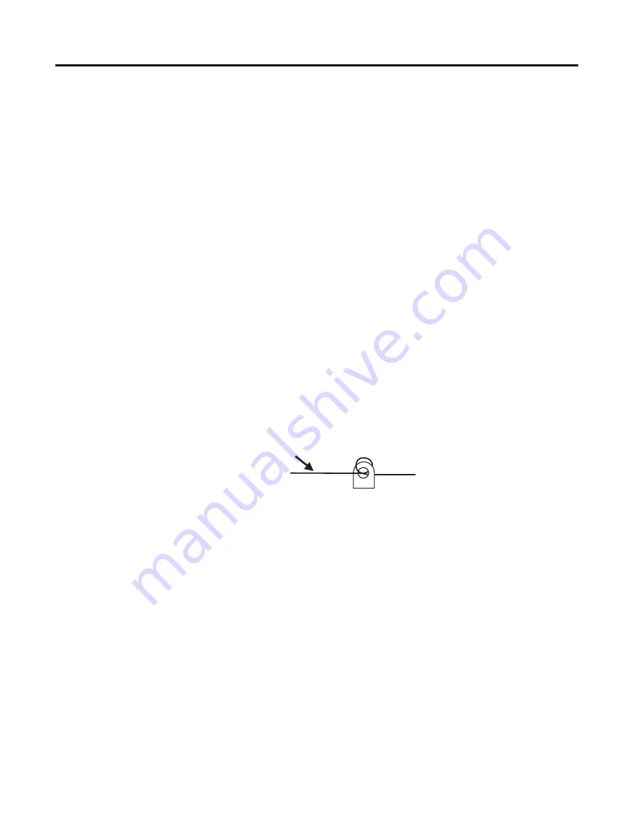
of 10.0 A or more. If the heater current is too low, loop the load line
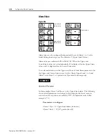
several times through a CT, as shown in the diagram below. Looping it
through twice will double the detection current.
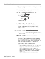
Figure 3.94 — Loop Load Line
Installing Current Transformers (CT)
This function can be used with 900-TC8 controller models that have the HBA,
HSA, and HOA alarms and 900-TC16 controllers with the heater
burnout/heater short/heater overcurrent option unit installed.
For the 900-TC16, connect the CT in advance to terminals 14 and 15 (CT1), or
13 and 15 (CT2). For the 900-TC8, connect the CT in advance to terminals 14
and 15 (CT1) or 15 and 16 (CT2). Then pass the heater power line through the
CT's hole.
For specifications, models and dimensions of current transformers that can be
used with this Controller, refer to Appendix A.
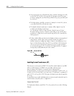
Single-phase Heaters
For single-phase heaters, install the CT in the position shown in the following
diagram.
CT
Load Line
Summary of Contents for Allen-Bradley 900-TC16
Page 1: ...USER MANUAL Bulletin 900 TC8 900 TC16 900 TC32 Series B Temperature Controllers...
Page 2: ...2...
Page 72: ...Publication 900 UM007D EN E January 2011 3 2 Configuration Basic Operation Figure 3 3 900 TC32...
Page 136: ...Publication 900 UM007D EN E January 2011 3 66 Configuration Basic Operation Notes...
Page 340: ...Publication 900 UM007D EN E January 2011 5 112 Parameter Functions Definitions Notes...
Page 350: ...Publication 900 UM007D EN E January 2011 6 10 Troubleshooting Error Indication Notes...
Page 406: ...Publication 900 UM007D EN E January 2011 D 8 Glossary Notes...


