Publication 900-UM007D-EN-E - January 2011
Parameter Adjustments & Application Considerations
4-5
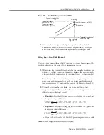
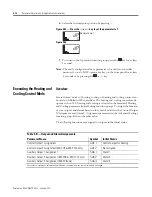
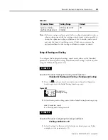
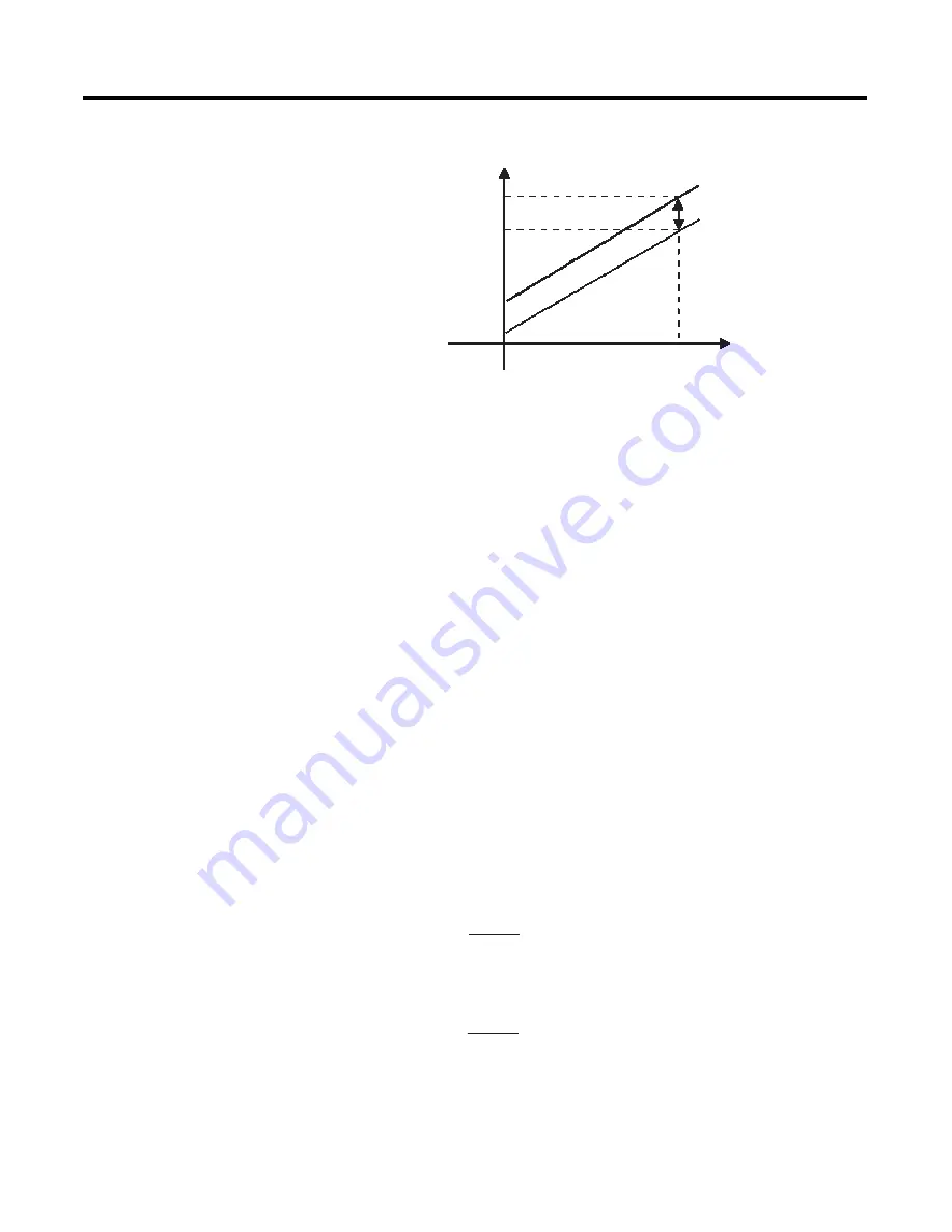
Figure 4.12 — One-Point Temperature Input Shift
3.
After you have configured the 1-point input shift value, check the
controller readout (A) and control target temperature (B). If they are
almost the same, this completes temperature input shift procedure.
Using the 2-Point Shift Method
Use the 2-point input shift method if you want to increase the accuracy of the
readout values across the range of your temperature sensor.
1.
When using the 2-point shift method, shift the controller readout at two
points: — the first, near room temperature
and —
the second, near the
value at which the temperature of the control target is to be controlled.
Therefore, for this procedure, bring the control target temperature to
near room temperature and to near the set point, and check control
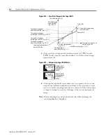
target temperature (B) and controller readout (A). Refer to Figure 4.10
2.
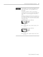
Using the equations below, calculate the upper- and lower-limit
temperature input shift values from the readout and temperature to be
shifted that you obtained in step 1.
– Equation 1:
Use the following equation to calculate the Lower-Limit
temperature input shift value.
– Equation 2:
Use the following equation to calculate the Upper-Limit
temperature input shift value.
–
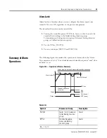
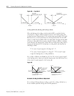
Figure – shows the effect of shift by 2-point temperature input shift.
Note:
For meanings of variables, refer to Figure –.
Controller readout (A)
Temperature readout
after shift (e.g. 120
°
C)
Temperature readout
before shift (e.g. 110
°
C)
After shift
Input shift value (e.g. 10
°
C)
Before shift
Near set point
(e.g. 120
°
C)
Temperature readout of
control target (B)
0
insl
=
YL
−
Y1
Y2
−
Y1
×
{(X2
−
Y2)
−
(X1
−
Y1)} + (X1
−
Y1)
insh
=
YH
−
Y1
Y2
−
Y1
×
{(X2
−
Y2)
−
(X1
−
Y1)} + (X1
−
Y1)
Summary of Contents for Allen-Bradley 900-TC16
Page 1: ...USER MANUAL Bulletin 900 TC8 900 TC16 900 TC32 Series B Temperature Controllers...
Page 2: ...2...
Page 72: ...Publication 900 UM007D EN E January 2011 3 2 Configuration Basic Operation Figure 3 3 900 TC32...
Page 136: ...Publication 900 UM007D EN E January 2011 3 66 Configuration Basic Operation Notes...
Page 340: ...Publication 900 UM007D EN E January 2011 5 112 Parameter Functions Definitions Notes...
Page 350: ...Publication 900 UM007D EN E January 2011 6 10 Troubleshooting Error Indication Notes...
Page 406: ...Publication 900 UM007D EN E January 2011 D 8 Glossary Notes...


