Publication 900-UM007D-EN-E - January 2011
4-14
Parameter Adjustments & Application Considerations
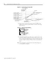
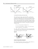
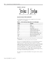
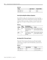
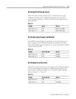
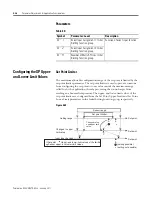
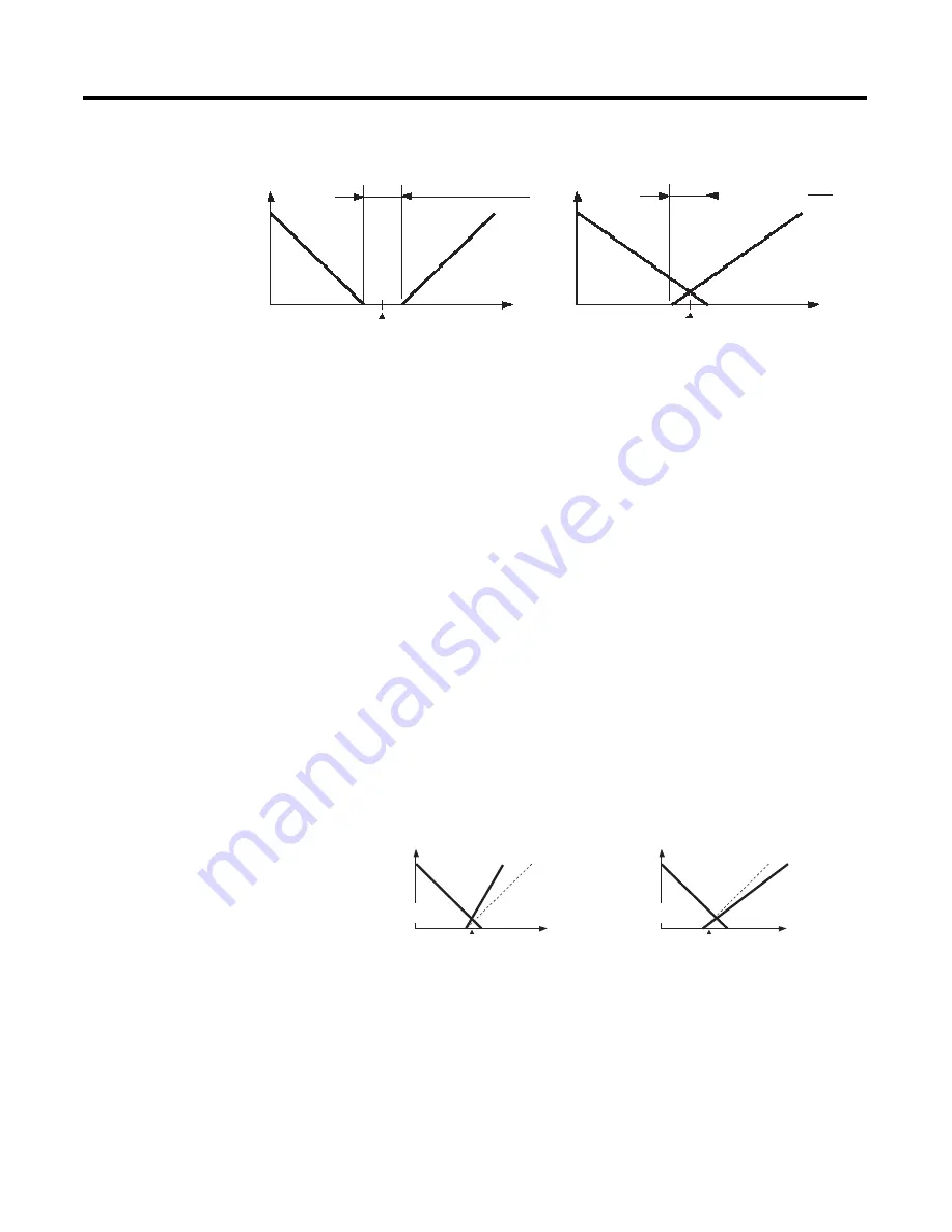
Figure 4.26 — Dead Band
Cooling Coefficient (Heating and Cooling Control)
When the heating and cooling control mode and PID control method are
selected, the Cooling Coefficient parameter can be used. If the heating and
cooling functional characteristics of the control target greatly differ, this could
limit satisfactory control performance from being obtained by the same PID
values. To reduce the possibility of this occurring, adjust the proportional band
(P) at the cooling side of the set point using the cooling coefficient to balance
control between the heating and cooling sides. In heating and cooling control
the proportional band, (P) at the heating or cooling side is calculated by the
following formula:
P for control output assigned to heating side = P
P for control output assigned to cooling side = P for control output
assigned to heating side
×
cooling coefficient
The cooling coefficient is multiplied by the P for the control output assigned
to the heating side to obtain control with characteristics that differ from those
of the control output assigned to the heating side.
Figure 4.27
Automatic Cooling Coefficient Adjustment
By executing AT during heating/cooling control, the cooling coefficient can
be automatically calculated along with the PID parameters.
Output
Heating side
Dead band:
dead band width = positive
Cooling side
Set point
Output
Heating side
Cooling side
Overlap band:
dead band width = negative
Set point
PV
PV
PV
0
PV
0
Output
Output
P for control output
assigned to heating side
P for control output
assigned to heat-
ing side
×
1.0
P for control output
assigned to cooling side
Set point
P for control output assigned to
heating side
×
0.8
P for control output
assigned to heating side
P for control output
assigned to heat-
ing side
×
1.0
P for control output
assigned to cooling side
P for control output assigned to
heating side
×
1.5
Summary of Contents for Allen-Bradley 900-TC16
Page 1: ...USER MANUAL Bulletin 900 TC8 900 TC16 900 TC32 Series B Temperature Controllers...
Page 2: ...2...
Page 72: ...Publication 900 UM007D EN E January 2011 3 2 Configuration Basic Operation Figure 3 3 900 TC32...
Page 136: ...Publication 900 UM007D EN E January 2011 3 66 Configuration Basic Operation Notes...
Page 340: ...Publication 900 UM007D EN E January 2011 5 112 Parameter Functions Definitions Notes...
Page 350: ...Publication 900 UM007D EN E January 2011 6 10 Troubleshooting Error Indication Notes...
Page 406: ...Publication 900 UM007D EN E January 2011 D 8 Glossary Notes...

