Publication 900-UM007D-EN-E - January 2011
4-50
Parameter Adjustments & Application Considerations
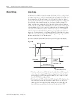
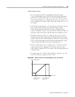
Determining the LBA Detection Time
To manually configure the LBA detection time, configured the LBA Detection
Time parameter to twice the LBA reference time given in the example below.
EXAMPLE
Procedure
1.
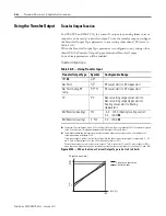
Set the output to the maximum value.
2.
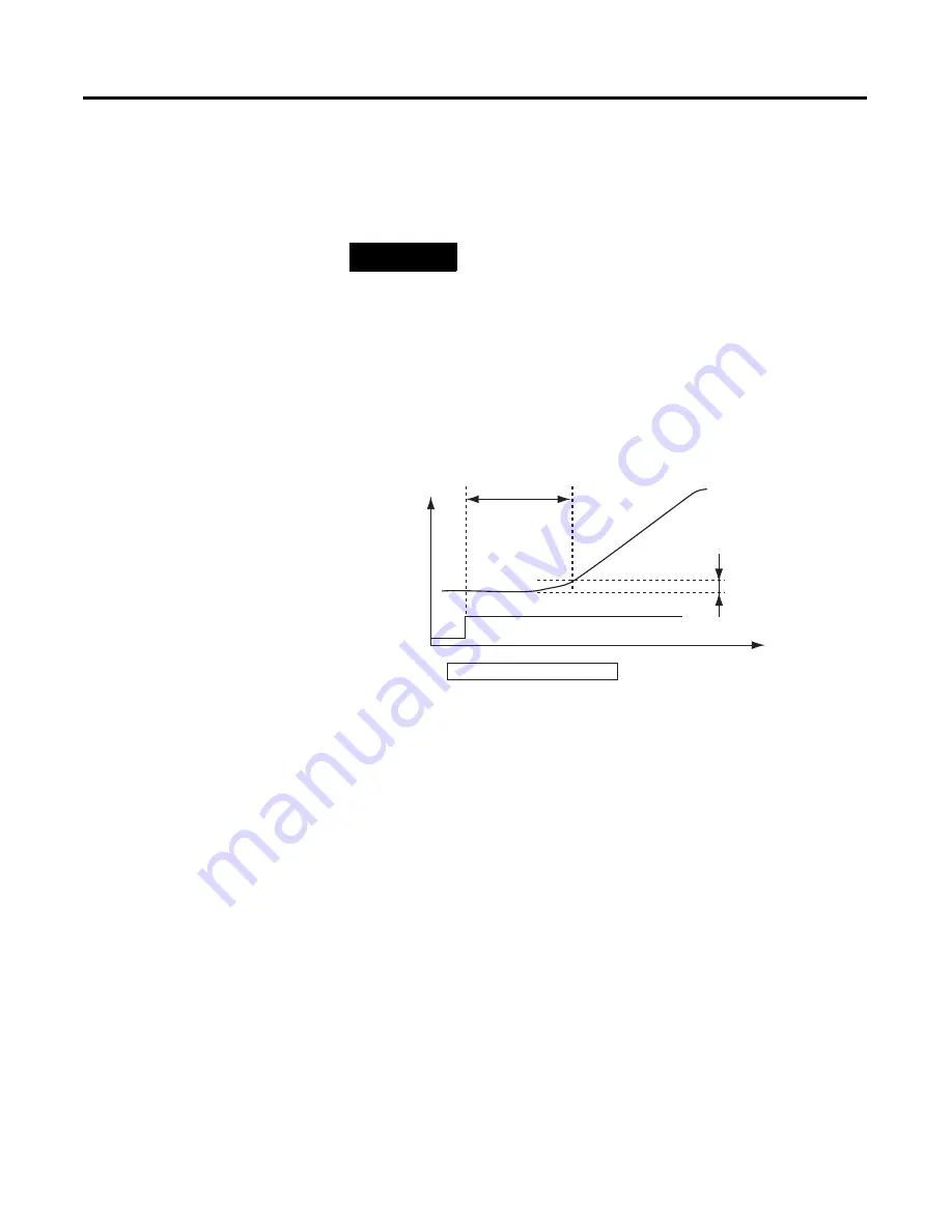
Measure the time required for the change in the input to reach the LBA
band.
Figure 4.95
3.
Set the LBA Detection Time parameter to two times the measured time.
LBA Level
Configure the control deviation when the control loop is working properly.
The default is 8.0 (
°
C/
°
F) for Controllers with Thermocouple/Resistance
Thermometer Multi-Inputs and 10.00% FS for Controllers with Analog
Inputs.
LBA Band
There is assumed to be an error in the control loop if the control deviation is
greater than the threshold configured for the LBA Level parameter and if the
control deviation does not change by at least the value configured for the LBA
Band parameter.
The default is 3.0 (
°
C/
°
F) for Controllers with Thermocouple/Resistance
Thermometer Multi-Inputs and 0.20% FS for Controllers with Analog Inputs.
MV = 100%
PV
Temperature
Time
Measurement time
Tm
LBA band
LBA detection time = Tm
×
2
Summary of Contents for Allen-Bradley 900-TC16
Page 1: ...USER MANUAL Bulletin 900 TC8 900 TC16 900 TC32 Series B Temperature Controllers...
Page 2: ...2...
Page 72: ...Publication 900 UM007D EN E January 2011 3 2 Configuration Basic Operation Figure 3 3 900 TC32...
Page 136: ...Publication 900 UM007D EN E January 2011 3 66 Configuration Basic Operation Notes...
Page 340: ...Publication 900 UM007D EN E January 2011 5 112 Parameter Functions Definitions Notes...
Page 350: ...Publication 900 UM007D EN E January 2011 6 10 Troubleshooting Error Indication Notes...
Page 406: ...Publication 900 UM007D EN E January 2011 D 8 Glossary Notes...


