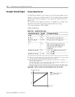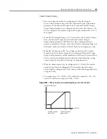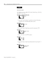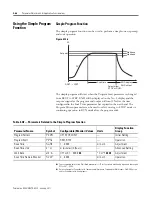
Publication 900-UM007D-EN-E - January 2011
4-76
Parameter Adjustments & Application Considerations
Note:
The order of priority is as follows: Manual MV > MV at stop > MV at
PV error.
MV at PV Error
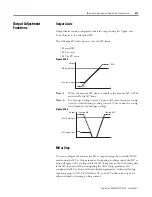
You can configure the amount the MV is output during an input error
condition. The MV at stop takes priority when stopped and the manual MV
takes priority in manual mode.
Note:
The order of priority is as follows: Manual MV > MV at stop > MV at
PV error.
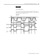
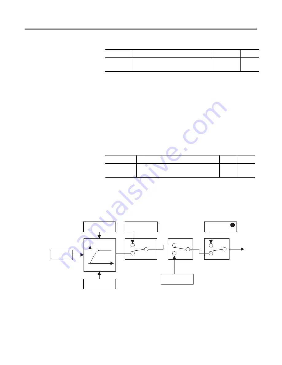
The order of priority of the MVs is illustrated in the following diagram.
Figure 4.166
Table 4.AH
Parameter Configurable Range
Unit
Default
MV at Stop
−
5.0…105.0 for standard control
−
105.0…105.0 (heating/cooling control)
%
0.00
Table 4.AI
Parameter
Configurable Range
Unit
Default
MV at PV error
−
5.0…105.0 for standard control
−
105.0…105.0 (heating/cooling control)
%
0.0
PID
calculations
MV upper limit
Manipulated variable
Time
MV lower limit
MV at PV Error
Input error
RUN/STOP
MV at Stop
Manual MV
Auto/manual switch
Output
1
Summary of Contents for Allen-Bradley 900-TC16
Page 1: ...USER MANUAL Bulletin 900 TC8 900 TC16 900 TC32 Series B Temperature Controllers...
Page 2: ...2...
Page 72: ...Publication 900 UM007D EN E January 2011 3 2 Configuration Basic Operation Figure 3 3 900 TC32...
Page 136: ...Publication 900 UM007D EN E January 2011 3 66 Configuration Basic Operation Notes...
Page 340: ...Publication 900 UM007D EN E January 2011 5 112 Parameter Functions Definitions Notes...
Page 350: ...Publication 900 UM007D EN E January 2011 6 10 Troubleshooting Error Indication Notes...
Page 406: ...Publication 900 UM007D EN E January 2011 D 8 Glossary Notes...

