Publication 900-UM007D-EN-E - January 2011
5-70
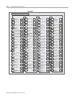
Parameter Functions & Definitions
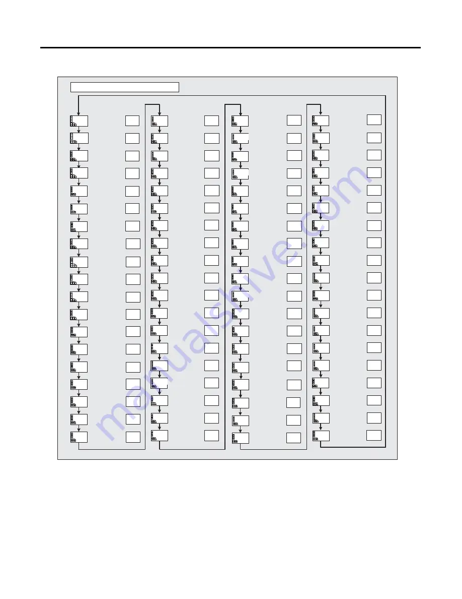
Figure 5.10
M
M
M
a1lt
off
M
M
M
M
M
M
M
M
M
M
M
M
cmov
0
M
M
hsu
on
M
M
M
M
M
M
M
M
hsl
off
hsh
0.1
lba
0
lbal
8.0
lbab
3.0
out1
o
out2
none
sub1
alm1
M
M
M
M
M
M
sub2
alm2
csel
on
t-u
m
sub3
alm3
alsp
sp-m
M
M
manl
off
pvrp
4
M
M
M
M
M
M
M
och
0.1
pf
a-m
pfd1
1
pfd2
0
pfd3
0
pfd4
0
pfd5
0
M
M
M
M
M
M
spdp
4
pvdp
on
ra1m
0
odsl
o
ra2m
0
M
M
M
M
ra1
0
rac
0
ra2
0
M
M
a2lt
off
M
M
M
M
M
a3lt
prlt
3
sero
off
cjc
on
M
M
M
M
M
M
M
M
M
M
M
rlrv
off
colr
red
a1on
0
a2on
0
a3on
0
a1of
0
a3of
0
istp
in51
pv-b
c
°
5.0
mvse
off
a2of
0
M
M
M
M
svst
off
pvst
off
M
M
M
M
amad
off
rt
off
RT
M
csca
off
M
ocu
on
ocl
off
sb1n
n-o
sb2n
n-o
sb3n
n-o
at-g
0.8
at-h
lcma
20.0
inf
0.0
pvad
off
o-dp
off
ret
off
M
M
M
M
M
d.ref
0.25
Advanced Setting Function Group
init
off
Parameter
Initialization
mspu
off
Multi-SP Uses
spru
m
SP Ramp Time
Unit
Standby
Sequence
Reset
rest
a
Auxiliary Output
1 Open in Alarm
Auxiliary Output
2 Open in Alarm
Auxiliary Output
3 Open in Alarm
HB ON/OFF
hbu
on
Heater Burnout
Latch
hbl
off
Heater Burnout
Hysteresis
hbh
0.1
ST Stable
Range
st-b
15.0
C
α
alfa
0.65
AT Calculated
Gain
AT Hysteresis
0.8
C
Limit Cycle MV
Amplitude
Input Digital
Filter
Additional PV
Display
MV Display
Alarm 1 Latch
Alarm 2 Latch
Alarm 3 Latch
off
Move to Protect
Level Time
Input Error
Output
Cold Junction
Compensation
Method
MB Command
Logic Switching
PV Change
Color
PV Stable
Band
Alarm 1 ON
Delay
Alarm 2 ON
Delay
Alarm 3 ON
Delay
Alarm 1 OFF
Delay
Alarm 2 OFF
Delay
Alarm 3 OFF
Delay
Input Shift Type
MV at Stop and
Error Addition
Auto/Manual
Select Addition
HS Alarm Use
HS Alarm Latch
HS Alarm
Hysteresis
LBA Detection
Time
LBA Level
C
LBA Band
C
Control Output 1
Assignment
Control Output 2
Assignment
Auxiliary Output 1
Assignment
Auxiliary Output 2
Assignment
Auxiliary Output 3
Assignment
Character
Select
Soak Time Unit
Alarm SP
Selection
Manual MV Limit
Enable
PV Rate of
Change Calculation
Period
Automatic Cooling
Coefficient
Adjustment
Heater
Overcurrent
Use
Heater
Overcurrent
Latch
Automatic
Display Return
Time
Move to
Calibration
function group
ON/OFF Counter
Reset
Control Output 2
ON/OFF Count
Alarm Set Value
Control Output 1
ON/OFF Count
Alarm Set Value
Control Output 2
ON/OFF Count
Monitor
Control Output 1
ON/OFF Count
Monitor
Display Refresh
Period
PV Status
Display Function
SV Status
Display Function
MV Display
Selection
PV Decimal
Point Display
PV/SP Display
Screen Selection
Monitor/Setting
Item 5
Monitor/Setting
Item 4
Monitor/Setting
Item 3
PF Setting
Monitor/Setting
Item 1
Monitor/Setting
Item 2
Heater
Overcurrent
Hysteresis
5-71
5-71
5-71
5-72
5-73
5-73
5-73
5-74
5-75
5-76
5-74
5-75
5-77
5-77
5-80
5-81
5-82
5-82
5-82
5-84
5-85
5-85
5-85
5-86
5-86
5-86
5-86
5-87
5-88
5-89
5-89
5-90
5-90
5-91
5-92
5-93
5-93
5-94
5-95
5-96
5-96
5-97
5-77
5-77
5-78
5-79
5-79
5-79
5-97
5-98
5-98
5-100
5-101
5-102
5-102
5-102
5-102
5-102
5-103
5-103
5-104
5-105
5-105
5-106
5-107
5-107
5-107
5-108
5-108
5-109
5-99
5-99
5-78
5-79
5-87
5-88
Summary of Contents for Allen-Bradley 900-TC16
Page 1: ...USER MANUAL Bulletin 900 TC8 900 TC16 900 TC32 Series B Temperature Controllers...
Page 2: ...2...
Page 72: ...Publication 900 UM007D EN E January 2011 3 2 Configuration Basic Operation Figure 3 3 900 TC32...
Page 136: ...Publication 900 UM007D EN E January 2011 3 66 Configuration Basic Operation Notes...
Page 340: ...Publication 900 UM007D EN E January 2011 5 112 Parameter Functions Definitions Notes...
Page 350: ...Publication 900 UM007D EN E January 2011 6 10 Troubleshooting Error Indication Notes...
Page 406: ...Publication 900 UM007D EN E January 2011 D 8 Glossary Notes...

