background image

Publication 900-UM007D-EN-E - January 2011

5-94

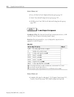
Parameter Functions & Definitions

Related Parameter

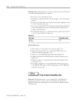
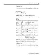
Program Pattern (Initial Setting function group, page 5-57)

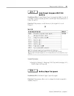
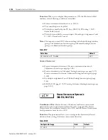
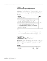
Auxiliary Output 2 Assignment 
(900-TC8, 900-TC16)

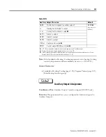
Conditions of Use:

 Auxiliary Output 2 must be assigned.

Function:

 This parameter allows you to configure the function assigned to 

Auxiliary Output 2.

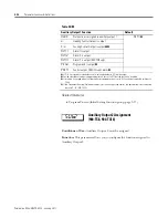
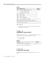
Table 5.DM 

Auxiliary Output 1 Function

Default

none

:

No function is assigned to auxiliary output 1

alm1

 ➌

o

:

Heating Control Output is output

c-o

:

Cooling Control Output is output 

➊➍ 

alm1

:

Alarm 1is output

alm2

:

Alarm 2 is output

alm3

:

Alarm 3 is output (900-TC8 only)

p.end

:

Program end is output 

ralm

:

Control output ON/OFF count alarm 

 If 

c-o

 is assigned for standard control, a value equivalent to 0% will be output. 

 Can be selected only when the program pattern is not set to OFF, but the function is disabled.

 If a setting is changed when the Program Pattern parameter is not set to OFF, control automatically switches to 

p.end

➍ 

If the Standard or Heating/Cooling parameter is set to heating/cooling control, this parameter will automatically 

be set to 

c-6 

(900-TC32).

sub2

Summary of Contents for Allen-Bradley 900-TC16

Page 1: ...USER MANUAL Bulletin 900 TC8 900 TC16 900 TC32 Series B Temperature Controllers...

Page 2: ...2...

Page 3: ...I 1 1 Safety Guidelines for the Application Installation and Maintenance of Solid State Control available from your local Allen Bradley sales office describes some important differences between solid...

Page 4: ...uirements Electrical Equipment for Control Measurement and Laboratory Use This product is intended for use in an industrial environment Low Voltage Directive This product is tested to meet Council Dir...

Page 5: ...P vi Characteristics P vi Communications Characteristics P vii Other Upgrades P viii Option Units P ix How to Read Display Symbols P x Chapter 1 Bulletin 900 Input Output Overview I O Configurations M...

Page 6: ...t Type 3 12 Input Type 3 12 Selecting C F 3 14 Temperature Units 3 14 Configuring the SP 3 15 Changing the SP 3 15 Selecting PID Control or ON OFF Control 3 16 Overview 3 16 2 PID Control 3 16 ON OFF...

Page 7: ...Considerations Shifting Input Values 4 1 1 Point Uniform Shift 4 1 2 Point Shift 4 3 How to Calculate Input Shift Values 4 3 Using the 1 Point Shift Method 4 4 Using the 2 Point Shift Method 4 5 Alar...

Page 8: ...Key Protect 4 33 PV Color Change 4 39 PV Color Change Function 4 39 Setting 4 42 Alarm Delays 4 44 Alarm Delays 4 44 Loop Break Alarm 4 47 Loop Break Alarm LBA 4 47 Performing Manual Control 4 53 Manu...

Page 9: ...l Switch 5 10 Multi SP Set Point 0 3 5 10 Set Point During SP Ramp 5 10 Heater Current 1 Value Monitor 5 11 Heater Current 2 Value Monitor 5 12 Leakage Current 1 Monitor 5 13 Leakage Current 2 Monitor...

Page 10: ...ak Time 5 39 Wait Band 5 40 MV at Stop 5 40 MV at PV Error 5 41 SP Ramp Set Value 5 41 MV Manipulated Variable Upper Limit MV Manipulated Variable Lower Limit 5 42 MV Upper Limit 5 42 MV Lower Limit 5...

Page 11: ...Alarm 1 to 3 5 73 HB ON OFF 900 TC8 900 TC16 5 74 Heater Burnout Latch 900 TC8 900 TC16 5 74 Heater Burnout Hysteresis 900 TC8 900 TC16 5 75 ST Self Tuning Stable Range 5 75 5 76 AT Calculated Gain 5...

Page 12: ...Heater Overcurrent Latch 900 TC8 900 TC16 5 99 Heater Overcurrent Hysteresis 5 100 900 TC8 900 TC16 5 100 PF Setting 5 101 Monitor Setting Item 1 to 5 5 102 PV SP Display Screen Selection 5 103 MV Di...

Page 13: ...e A 5 Current Transformer CT A 7 Specifications A 7 Approximate External Dimensions A 7 Sensor Input Setting and Indication Ranges A 9 Control Range A 10 Appendix B Parameter Operations List B 1 Funct...

Page 14: ...5V DC Input 900 TC8 900 TC16 C 16 Checking Indication Accuracy C 18 Checking Accuracy of a Thermocouple or Non Contact Temperature Sensor C 18 Checking Indication Accuracy of a Platinum Resistance Th...

Page 15: ...it for engineering units such as C m and g The size of EU varies according to the Input Type For example when the input temperature setting range is 200 1300 C 1 EU is 1 C and when the input temperatu...

Page 16: ...he upgraded controllers are basically compatible with the previous controllers Terminal arrangements terminal sizes and panel mounting depth have not been changed 900 TC32x Model numbers have changed...

Page 17: ...and MV ALM indicator was changed to SUB indicator 900 TC32 Display Segments PV 7 segments SV 7 segments Character Heights PV 7 mm SV 3 5 mm Display Segments PV 11 segments SV 11 segments Character Hei...

Page 18: ...7 8 CT2 One CT Two CTs Voltage output Long life relay output CT1 12 VDC 21mA A B B V mA 250 VAC 3 A Analog input TC Pt universal input Control Output 2 Control Output 2 Resistive load 14 15 14 15 14 1...

Page 19: ...nput sensor types for thermocouple inputs The following types of thermocouple input were added W and PLII Input range for E thermocouple 0 600 C Input range increased for E thermocouple 200 600 C Inpu...

Page 20: ...mocouple 0 3 PV or 1 C whichever is greater 1 digit Platinum resistance thermometer 0 2 PV or 08 C whichever is greater 1 digit Analog input 0 2 FS digit Influence of signal source resistance Thermoco...

Page 21: ...F Characteristics Series A Series B Table P G Series A Series B Communication Access Size Double word access only Word access and double word access Communication Service Composite Read from Variable...

Page 22: ...y Note The mounting bracket for the Series A models cannot be used for Series B models Terminal Cover for 900 TC16 Note The terminal covers for the Series A models cannot be used for Series B models T...

Page 23: ...485 communications with 3 phase heater burnout open and heater short circuit failure detection 900 TC16NCOMP3 B Communications and Second Voltage SSR Output Unit RS 485 communications and a second vol...

Page 24: ...to alphabet characters Table P J 11 Segment Display Selection The Character Select parameter in the Advanced Setting function group can be turned OFF to display the following 7 segment characters Tabl...

Page 25: ...T1 Input CT2 Input Event Inputs 2 Channels Set point input functions from external digital switches RUN STOP Program Start Auto Manual Control Output Heating Control Output Cooling Control Ouput 1 Con...

Page 26: ...annels Set point input functions from external digital switches RUN STOP Program Start Auto Manual Control Section Control Output Heating Control Output Cooling Auxillary Output 2 Auxillary Output 1 A...

Page 27: ...ol Select AT Auto Tuning and ST Self Tuning as tuning functions Use multi SP switch between automatic and manual operation start reset the simple program function and initiate the RUN STOP function ac...

Page 28: ...r an On Off electro mechanical relay EMR ON OFF triac output AC only On Off voltage input to solid state relay output or analog current DC 4 20 mA or 0 20 mA output Refer to Table 1 B or 1 D Triac Rel...

Page 29: ...900 UM007D EN E January 2011 Bulletin 900 Input Output Overview 1 5 Figure 1 4 Triac Diagram Select a surge absorber that satisfies the following conditions 1 2 Triac Relay Output Varistor Varistor In...

Page 30: ...be achieved by event input Multiple set point selection multi SP max 4 points RUN STOP mode change switching between automatic and manual operation and starting stopping the simple program Refer to T...

Page 31: ...Publication 900 UM007D EN E January 2011 Bulletin 900 Input Output Overview 1 7 Controller Hardware Versions The following tables provide a list of controller base features with associated Cat Nos...

Page 32: ...or RTD 100 240V AC Relay On Off NA Yes 1 Phase 900 TC8RGTH1Z25 NA No 900 TC8RGTZ25 Volt On Off SSR No 900 TC8RVGTZ25 NA Yes 3 Phase 900 TC8RGTH3Z25 Volts On Off SSR NA Yes 1 Phase 900 TC8VGTH1Z25 NA...

Page 33: ...e Cat No for Enhanced 900 TC16 Line 1 16th DIN 2 Thermocouple or RTD 100 240V AC Relay On Off 900 TC16RGTZ25 Triac On Off 3 A 900 TC16YGTZ25 Volts On Off SSR 900 TC16VGTZ25 Analog Current 900 TC16ACGT...

Page 34: ...e HB Yes 900 TC16P1V2 Series B option units must be used with Series B controllers DO NOT use series B option units with Series A controllers DIN Size in mm Number of Alarms Sensor Input Type Power Su...

Page 35: ...lletin 900 TC16 PF A M MV SV PV SUB2 SUB3 STOP OUT1 MANU CMW OUT2 SUB1 HA Operation Indicators Temperature Unit Operation Indicators Mode Key No 1 Display No 2 Display No 3 Display Up Key Down Key Fun...

Page 36: ...d during startup No 2 Displays the Set Point parameter operation read value manipulated variable or during configuration the value of the displayed No 1 display parameter No 3 900 TC8 only Displays MV...

Page 37: ...utput only OUT2 Control Output 2 900 TC8 and 900 TC16 Only Lights when the control output function assigned to control output 2 turns ON For a current output however OFF for a 0 output only STOP Opera...

Page 38: ...nction group Mode Select Press this key to select the various parameters within each function group The selection of parameters can be reversed by holding this key down Up Each press of this key incre...

Page 39: ...C16 and 900 TC32 is 1 to 5 mm and the 900 TC8 is 1 to 8 mm Note Dimensions are in millimeters Dimensions are not intended to be used for manufacturing purposes To convert millimeters to inches multipl...

Page 40: ...Figure 2 3 900 TC32 Panel Cutout Dimensions Dimensions are in millimeters Dimensions are not intended to be used for manufacturing purposes Figure 2 4 900 TC8 48 35 24 99 44 8 22 2 1 2 3 4 5 6 7 8 9...

Page 41: ...Publication 900 UM007D EN E January 2011 Preparations 2 3 Figure 2 5 900 TC16 Figure 2 6 900 TC32 48 number of units 2 5 45 60 min 45 45 x 60 min...

Page 42: ...sients in temperature at the terminal block may result in a measurement error System Wiring and Installation Guidelines ATTENTION Risk of Electrical Shock Devices are Open Type Listed Process Control...

Page 43: ...he Bulletin 900 Controller If the settings are not appropriate for the control target the controller may operate in an unexpected manner resulting in damage to the product or personal injury To mainta...

Page 44: ...the Bulletin 900 Controller Ensure that enough space is left for the heat to escape Do not block the ventilation holes on the casing Cleaning Do not use paint thinner or the equivalent Use standard gr...

Page 45: ...anel mounting adapters along the Bulletin 900 TC8 body from the rear of the case up to the panel and fasten temporarily ATTENTION Store within the following temperature and humidity ranges Temperature...

Page 46: ...nd devices that generate powerful high frequency noise e g high frequency welders high frequency sewing machines or surges 7 Install the controller so that it is horizontal can read the display proper...

Page 47: ...pry and pullout the front panel slightly Then pull out on the front panel gripping both sides Be sure not to impose excessive force on the panel Setting Up the 900 TC8 Controller with the Optional Un...

Page 48: ...controller is pushed all the way in removing any gap between the controller panel and adapter Finally use the two screws on the adapter to secure the unit in place The recommended panel thickness is...

Page 49: ...machines or surges 7 Install the controller so that it is horizontal can read the display properly How to Attach the 900 TC16 Wiring Terminal Block Cover Figure 2 11 Make sure that the UP mark on the...

Page 50: ...er Figure 2 12 Note When you remove the internal mechanism from the housing never touch electric components inside or subject the internal mechanism to shock Table 2 B Function 900 TC16 Option Module...

Page 51: ...roof packing is not necessary when there is no need for the waterproofing function 1 For waterproof mounting Install waterproof packing on the controller 2 Insert the 900 TC32 into the mounting hole i...

Page 52: ...ller can be replaced by removing the terminal block from the 900 TC32 Figure 2 14 1 Insert a flat blade screwdriver into the tool holes one on the top and one on the bottom to release the hooks Do not...

Page 53: ...utput 2 Voltage output for driving SSR 12 VDC 21 mA Control output 1 Triac output 250 VAC 3 A resistive load Communications 900 TC8COM RS 485 B 11 12 DO NOT USE 13 900 TC8232 RS 232C SD 11 RD 12 SG 13...

Page 54: ...er Power Supply Supply Control Control Output 1 Output 1 Auxillary Auxillary Output 1 Output 1 DO NOT DO NOT USE USE A B B Universal TC Pt Input DO NOT DO NOT USE USE B A RS 495 Communications Relay O...

Page 55: ...gth 5 6 mm For 900 TC8 900 TC16 Tighten the terminal screws properly Tighten them to a torque 0 74 0 9 N m 6 6 8 lb in Loose screws may cause malfunction For 900 TC32 Tighten the terminal screws to a...

Page 56: ...ect to terminals 9 and 10 The following table shows the specifications Table 2 C Input Power Supply Bulletin 900 TC8 Bulletin 900 TC16 100 240V AC 50 60 Hz 10VA 7 5VA 24V AC 50 60 Hz 5 5VA 5VA 24V DC...

Page 57: ...s a large error in the measurement values make sure that the correct sensor type is configured and for thermocouples that input compensation has been properly configured RTDs can be either 2 or 3 wire...

Page 58: ...power leads or in the same wiring path Other methods such as separating conduits and wiring ducts or using shield wire are also effective and recommended Wiring Control Output 1 The following diagrams...

Page 59: ...600 max Resolution Approx 10 000 Table 2 E 900 TC16 Output Type Output 1 Specifications Relay 250V AC 3 A resistive load electrical durability 100 000 operations Triac AC relay 250V AC 3 A resistive l...

Page 60: ...ncy If an output relay is used beyond its life expectancy its contacts may become fused or burned Use the Bulletin 900 Controller within the rated load Not doing so may cause damage or fire Attach a s...

Page 61: ...internal circuits Figure 2 21 Option Unit 900 TC16P1V2 Option Unit 900 TC16NCOMV2 The following table shows the specifications for each output type Table 2 G Voltage Used Varistor Voltage Surge Resis...

Page 62: ...e not isolated Triac AC relay outputs use semiconductors for switching when closing and opening the circuit thereby eliminating relay chatter and arcing and improving durability compared to an electro...

Page 63: ...d 6 On the 900 TC32 when heating cooling control is used auxiliary output 1 becomes control output cooling When the HB the HS or heater overcurrent alarm is used with the 900 TC16 alarms are output ac...

Page 64: ...00 TC8 or Table 1 E for 900 TC16 If the heater burnout parameter function is used connect a current transformer CT across the terminals indicated in the following drawings in Figure 2 24 Figure 2 24 T...

Page 65: ...he following conditions The output current from the controller is approximately 7 mA 5V Contact input ON 1 K max OFF 100 K min Non contact input ON residual voltage 1 5V max OFF leakage current 0 1 mA...

Page 66: ...8 or larger Note To configure the 900 TC8 using RS232 communication optional software 900BuilderLite is available RS 485 Communication to a Personal Computer When the optional RS 485 communications un...

Page 67: ...Figure 2 29 To use a PC on an RS 485 link network connection a Bulletin 900 CONV RS 232 to RS 485 or equivalent converter is required Terminator 120 1 2 W Shielded Cable Abbr A B 1 mark A B 0 space No...

Page 68: ...th and connects to your PC s USB port and the controller s direct communication port refer to Figure 3 900BuilderLite is used with the cable to configure the 900 TC8 900 TC16 or 900 TC32 controller 90...

Page 69: ...ecting the cable 3 Install the driver Note The driver is available free of charge from the Bulletin 900 Temperature Controller Website www ab com industrialcontrols products relays_timers_and_temp_ co...

Page 70: ...n methods refer to the user s manual for the 900 CPOEM1 Serial Conversion Cable When setting 900 BuilderLite for direct communication the port parameters of the direct communication port are fixed as...

Page 71: ...ey Temperature Unit Operation Indicators No 1 Display No 2 Display Up Key Function Group Key Down Key PF A M MV SV PV SUB2 SUB3 STOP OUT1 MANU CMW OUT2 SUB1 HA Operation Indicators Temperature Unit Op...

Page 72: ...Publication 900 UM007D EN E January 2011 3 2 Configuration Basic Operation Figure 3 3 900 TC32...

Page 73: ...displayed a m will flash after 1st second Operation Function Group Press the Key for at least 1 s Press the Key for at least 1 s Input password Input password while amoV is displayed Set value 169 Pr...

Page 74: ...when any of these four function groups are selected Protect Function Group To move to this function group simultaneously press the O and M keys for at least 3 seconds in the Operation Adjustment or M...

Page 75: ...configured for Monitor Setting Item 1 to 5 can be displayed You can move from the Monitor Setting Item to the Operation of Initial Setting function groups Only the 900 TC8 supports this function grou...

Page 76: ...return time event input assignments standby sequence and alarm hysteresis and it is the function group for moving to the user calibration Communications Setting Function Group To move to the Communica...

Page 77: ...ther leave the setting alone unchanged for at least 2 seconds or press the M key This loads the present value displayed into the controller s memory When another function group is selected the paramet...

Page 78: ...st 3 seconds to move from the Operation function group to the Initial Setting function group 2 Press the O key for less than 1 second to move from the Initial Setting function group to the Communicati...

Page 79: ...enus and the amount of time that you hold the keys down determines which configuration menu you move to This section describes two typical examples EXAMPLE Figure 3 7 Explanation of Examples Table 3 B...

Page 80: ...ifications Set control specifications Set alarm type Operation function group Set alarm values Start operation Power ON Operation function group PV SP Press the O key for at least 3 s Control stops In...

Page 81: ...he input type Input type Use the U and D keys to select PID control ON OFF control Use the U and D keys to set ST to OFF To execute ST PID control To cancel ST Check the control period Control period...

Page 82: ...your Bulletin 900 components at purchase to ensure it matches your input requirements refer to Tables 1 B and 1 D Input Type Example Operation Procedure Setting the Input Type to Thermocouple Type K...

Page 83: ...ermometer RTD Multi input Platinum Resistance Thermometer RTD Pt100 0 200 850 C 328 1 562 F 1 199 9 500 0 C 327 8 932 0 F 2 0 0 100 0 C 32 0 212 0 F JPt100 3 199 9 500 0 C 327 8 932 0 F 4 0 0 100 0 C...

Page 84: ...ration Procedure Select C 1 Press the O key for at least 3 seconds to move from the Operation function group to the Initial Setting function group Figure 3 13 Operation Function Group Figure 3 14 Init...

Page 85: ...cannot be changed when the Operation Adjustment Protection parameter is set to 3 For details refer to page 4 33 Using the Key Protect Function Group To change the set point press the U or D key in th...

Page 86: ...PID Control Controller configured selected P I and D Proportional Integral and Derivative control parameters are set by the AT Auto Tuning and ST Self Tuning parameters or by manual user setup For man...

Page 87: ...on to meet the needs of your application You can configure the individual control period values in the Control Period HEAT and Control Period COOL parameters Initial Setting function group Note The de...

Page 88: ...Initial Setting function group Note The Direct Reverse Operation parameter default is reverse operation EXAMPLE Operation Procedure In this example the Input Type Temperature Unit Direct Reverse Opera...

Page 89: ...lue refer to Table 3 A to match your desired sensor input Figure 3 23 3 Select the Temperature Unit parameter by pressing the M key Note The default is c C To configure f F press the U key Figure 3 24...

Page 90: ...ed Settings function group The default function assignment for each output is shown in Table 3 E Table 3 E Default Fuction Assignment Parameter Name Symbol Initial Status Control Output 1 Assignment o...

Page 91: ...ut heating Control output heating Control Output 2 Assignment out 2 Not assigned Not assigned Not assigned Control output cooling Auxiliary Output 1 Assignment sub 1 Alarm 1 Alarm 1 Alarm 1 Alarm 1 Au...

Page 92: ...meter to h c Heating Cooling Control Mode Note The following output assignments do not need to be set because they are set automatically as defaults by changing the control mode but they are shown her...

Page 93: ...the M key Figure 3 36 9 Press the U or D key to set c o When h c is selected for the Standard or Heating Cooling Control Mode parameter the setting will be c o Figure 3 37 10 Select the Auxiliary Out...

Page 94: ...he default is alm2 Figure 3 40 14 Press the O key for at least 1 second to move from the Advanced Setting to the Initial Setting function group Figure 3 41 15 Press the O key for at least 1 second to...

Page 95: ...Overview In the reverse operation ON OFF control method the control output MV turns OFF when the controlled temperature PV reaches the user defined set point When the control output MV turns OFF the...

Page 96: ...sis HEAT and Hysteresis COOL parameter functions respectively In standard heating or cooling control the HEAT Hysteresis setting is used as the hysteresis setting Adjustment function group regardless...

Page 97: ...Initial Setting function group Figure 3 45 2 Display the Input Type parameter in the Initial Setting function group Figure 3 46 Table 3 I Parameters Symbol Parameter Name and Group Location Applicati...

Page 98: ...ing Procedure In the second part of this example the set point is modified to 200 The set value i e the SP is shown on the controller s bottom display 1 Select the Process Value Set Point parameter in...

Page 99: ...roup Display parameter will be displayed in the adjustment function group Figure 3 52 3 Select the Hysteresis Heating parameter by pressing the M key Figure 3 53 4 Press the U and D keys to set the hy...

Page 100: ...eating and cooling control AT cannot be executed when control has stopped or during ON OFF control The results of AT are reflected in the Proportional Band P Integral Time I and Derivative Time D para...

Page 101: ...esis parameter configures the hysteresis when switching ON and OFF for the limit cycle operation during auto tuning Limit Cycle MV Amplitude The Limit Cycle MV Amplitude parameter configures the MV am...

Page 102: ...tude parameter is disabled at 100 AT Figure 3 60 Operation EXAMPLE Operation Procedure Execute 40 Auto Tuning AT Figure 3 61 Adjustment Function Group 1 Press the O Key to move from the Operation func...

Page 103: ...Self Tuning Figure 3 65 Self Tuning Function In the ST Self Tuning function the 900 TC controller continually executes step response tuning SRT from the start of program execution or when the set poi...

Page 104: ...ing ST execution and stops when it is complete Figure 3 67 Note When control characteristics are already known either from experience or previous use of the AT or ST parameter the individual PID param...

Page 105: ...ed Self Tuning ON 1 The set point at the start of program execution differs from the set point when the previous SRT was executed 2 The difference between the controlled temperature at start of progra...

Page 106: ...iting 2 seconds or pressing the O key RT Robust Tuning Figure 3 70 When Auto Tuning AT or Self Tuning ST is executed with Robust Tuning RT selected PID constants are automatically configured by the co...

Page 107: ...control object or sensor has slow response When hunting occurs in AT or ST for any reason Note PID constants are initialized to the factory settings when switching to RT When RT is selected the deriva...

Page 108: ...e Operation function group to the Initial Setting function group Figure 3 73 2 Select the Move to Advanced Setting function group parameter by pressing the M key Figure 3 74 3 Use the D key to enter 1...

Page 109: ...the Operation function group press the O key for at least 1 second Figure 3 78 Manual PID Setup The individual P I and D values can be manually set in the Proportional Band Integral Time and Derivativ...

Page 110: ...the M key Figure 3 80 3 Press the U or D key to set the Proportional Band parameter to 10 0 Figure 3 81 4 Select Integral Time by pressing the M key Figure 3 82 5 Press the U or D key to set the Inte...

Page 111: ...nd is Adjusted When P is increased The curve rises gradually and a long stable time is achieved preventing overshoot When P is decreased Overshoot and hunting occur however the set point is quickly re...

Page 112: ...larm output operation based on pre defined conditions using the Set Value number Note The following table describes the Alarm Type Alarm Value Upper Limit Alarm and Lower Limit Alarm parameters Table...

Page 113: ...nd Lower Limit hysteresis overlaps In case 3 the alarm is always OFF Set value 5 The alarm is always OFF if upper and Lower Limit alarm hysteresis with standby sequence overlaps 9 Absolute value Lower...

Page 114: ...To set alarm deviation use the Upper and Lower Limit Alarm parameters Set the Upper and Lower Limits in each of the Alarm Upper Limit 1 to 3 and Alarm Lower Limit 1 to 3 parameters Operation function...

Page 115: ...e parameter to 10 This value is loaded into memory by waiting 2 seconds or pressing the M key Figure 3 91 PV Change Rate Alarm The change width rate of change for PV input values can be found in any t...

Page 116: ...Heater burnout and heater overcurrent detection are executed by 1 measuring heater current with an optional current transformer single phase or 2 transformers 3 phase while the control output for hea...

Page 117: ...han the heater overcurrent detection current during the Ton period Current is increased when excessive current flows to the heater causing the heater overcurrent detection value to be exceeded and an...

Page 118: ...ze detection configure an alarm a current value difference of at least 1 0 A for heaters of less than 10 0 A and at least 2 5 A for heaters of 10 0 A or more If the heater current is too low loop the...

Page 119: ...into account when setting the detection current Figure 3 96 CT Installation Positions Delta Connecting Power Lines 2 For Star Y connecting power lines Refer to the following diagram for CT installatio...

Page 120: ...l of the heaters have the same current use the value when any one of them burns out Make sure that the following conditions are satisfied When using a heater with a normal load current of less than 10...

Page 121: ...tal current value for normal heater operation to 50 A or less When a current value of 55 0 A is exceeded ffff is displayed in the Heater Current 1 and 2 Value Monitor and Leakage Current 1 and 2 Monit...

Page 122: ...Connecting Lines The current when each phase is normal is 17 3 A 3 10 A Figure 3 101 Delta Connecting Lines The heater burnout current when there is a burnout at the load line is as follows heater bu...

Page 123: ...rent when each phase is normal is 5 8 A 10 A 1 3 Figure 3 103 Star Connecting Lines The heater burnout detection current for this connecting line is 5 4 A 5 8 5 2 CT CT L o a d L o a d 200 V 200 V 15...

Page 124: ...the load is as follows Heater burnout detection current 10 0 2 5 A To enable detection in either case use 7 5 A as the heater burnout detection current CT CT 200 V 200 V 5 A 5 A 200 V Load Load CT CT...

Page 125: ...the Adjustment function group EXAMPLE Operating Procedure Moving to the Advanced Setting Function Group In this example configure the Heater Burnout Detection 1 parameter to 2 5 The Heater Burnout De...

Page 126: ...3 108 3 Press the D key to enter the password 169 and move from the Initial Setting function group to the Advanced Setting function group The top parameter in the Advanced Setting function group is di...

Page 127: ...p Figure 3 112 3 Select the Heater Current 1 Value Monitor parameter by pressing the M key Check the current value Next set the Heater Burnout Detection 1 parameter Figure 3 113 4 Select the Heater Bu...

Page 128: ...O key for at least 3 seconds to move from the Operation function group to the Initial Setting function group Figure 3 116 2 Select Move to Advanced Setting function group by pressing the M key Figure...

Page 129: ...ustment function group Figure 3 121 3 Select the Leakage Current 1 Monitor parameter by pressing the M key Check the current value Next set the HS Alarm 1 parameter Figure 3 122 4 Select the HS Alarm...

Page 130: ...rameter is ON so set the Heater Overcurrent Detection 1 parameter Move to the Advanced Setting function group Press the O Key for at least three seconds to move from the Operation to the Initial Setti...

Page 131: ...tion group Figure 3 129 2 Press the O Key for less than one second to move from the Operation function group to the adjustment function group Figure 3 130 3 Press the M Key to select the Heater Curren...

Page 132: ...fer to MV Display for Heating and Cooling Control below When 1 2 5 or 6 is selected press the M Key to display the next value set for the PV SP display display 2 oc1 20 0 Table 3 Q PV SP Display Selec...

Page 133: ...r 2 a Monitor Setting Item Display parameter EXAMPLE PV SP MV and PV SP Multi SP on the Process Value Set Point Display This procedure displays PV SP MV and PV SP Multi SP on the Process Value Set Poi...

Page 134: ...ion parameter Figure 3 138 PV SP Display Screen 5 Use the U and D Keys to configure the parameter to a value of 2 Figure 3 139 6 Press the O Key for at least one second to move from the Advanced Setti...

Page 135: ...controller Note If the load is turned ON before the temperature controller correct self tuning and optimum control are no longer possible When operation is started after system warm up turn the power...

Page 136: ...Publication 900 UM007D EN E January 2011 3 66 Configuration Basic Operation Notes...

Page 137: ...Input Types There is no shift for analog inputs Use scaling for fine adjustments 1 Point Uniform Shift Overview Figure 4 1 With 1 point shift operation the Temperature Input Shift parameter Adjustment...

Page 138: ...2 Select the Temperature Input Shift parameter by pressing the M key Figure 4 5 Temperature Input Shift 3 Press the U or D key to set 1 Figure 4 6 Set Shift Parameter 4 To return to the Operation fun...

Page 139: ...hifted by an average of 1 5 C at the 50 input Set the Upper Limit value in the Upper Limit Temperature Input Shift Value parameter and the Lower Limit value in the Lower Limit Temperature Input Shift...

Page 140: ...ration when Compensating a Non Contact Infrared Temperature Sensor Using the 1 Point Shift Method Figure 4 11 1 In the temperature control configuration shown in Figure 4 10 bring the set point to nea...

Page 141: ...bring the control target temperature to near room temperature and to near the set point and check control target temperature B and controller readout A Refer to Figure 4 10 2 Using the equations below...

Page 142: ...full range of the sensor measurement range Note Before selecting these values check that they will not damage the control application if applied Controller readout A Set temperature upper limit YH e...

Page 143: ...t YH 260 C Check the temperature of the control target When the room temperature X1 is 25 C the readout on the controller Y1 is 40 C and when the temperature near the set point X2 is 110 C the readout...

Page 144: ...mporarily disabled until after the first alarm condition occurs From then on the alarm output is active for all future alarm conditions For example in a standard heating application if you used the st...

Page 145: ...tion group or Calibration function group 2 Use the PF key 900 TC8 3 Use an event input 900 TC8 and 900 TC16 Summary of Alarm Operations The following figure summarizes the operation of alarms when the...

Page 146: ...o configure the physical quantity to be expressed by the Upper Limit input value The Scaling Lower Limit parameter sets the physical quantity to be expressed by the Lower Limit value The Decimal Point...

Page 147: ...or at least 3 seconds to move from the Operation function group to the Initial Setting function group Figure 4 19 2 Select Scaling Upper Limit by pressing M Figure 4 20 3 Press the U or D key to set t...

Page 148: ...en h c heating and cooling is selected in the Standard Heating and Cooling parameter Initial Setting function group To assign the function of your outputs and alarms based on the control mode use the...

Page 149: ...parameter assignment is displayed because there is no control output The output set for the Auxiliary Output 1 Assignment parameter becomes the program END output unless the program pattern is OFF For...

Page 150: ...gned to cooling side P for control output assigned to heating side cooling coefficient The cooling coefficient is multiplied by the P for the control output assigned to the heating side to obtain cont...

Page 151: ...Band and Cooling Coefficient when using the PID method parameters EXAMPLE Operation Procedure Heating and Cooling Control Selection Standard or Heating and Cooling Heating and Cooling 1 Press the key...

Page 152: ...ion group Figure 4 30 2 Press the U key to set the parameter to 5 0 The setting range is 199 9 999 9 Figure 4 31 Using the Event Input Feature 900 TC8 900 TC16 Overview When the appropriate option uni...

Page 153: ...ation 100 AT Execute Cancel 40 AT Execute Cancel Setting Change Enable Disable and Alarm Latch Cancel Of these only the number of event inputs 0 to 2 set in the Number of Multi SP Uses parameter Initi...

Page 154: ...itch between two set points Set points 0 and 1 are specified by the status of event input 1 Figure 4 32 Event Inputs When you want to configure event inputs to change the controllers four pre set Set...

Page 155: ...can select Set Points 0 3 from the controller keypad by properly configuring the value of the Multi SP Uses parameter in the adjustment function group To change set points from the controller keypad...

Page 156: ...umber of Multi SP Uses parameter to 2 Multi SP 4 points Refer to Table 4 I Before you configure the Number of Multi SP Uses parameter you must first cancel protection from the Advanced Setting functio...

Page 157: ...e 4 35 Figure 4 36 4 Select Number of Multi SP Uses parameter by pressing the M key Figure 4 37 5 Press the U key to set the parameter to 2 This allows set point change from event input refer to Table...

Page 158: ...ram Start DRS Invert Direct Reverse Operation AT 2 100 AT Execute Cancel AT 1 40 AT Execute Cancel WTPT Setting Change Enable Disable or LAT Alarm Latch Cancel Turn event inputs ON and OFF while the p...

Page 159: ...Input Assignment 1 or Event Input Assignment 2 parameter is set to MANU auto manual manual control will start when Event Input 1 or 2 turns ON Auto control will start when the input turns OFF The MANU...

Page 160: ...AT Execute Cancel is set for either the Event Input Assignment 1 or Event Input Assignment 2 parameter 100 AT will be executed when event input 1 or 2 turns ON and will be cancelled when the input tu...

Page 161: ...ameter the setting change will be disabled when event input 1 or 2 turns ON and will be enabled when the input turns OFF Switching Alarm Latch Cancel When LAT Alarm Latch Cancel is set for either the...

Page 162: ...s of the set point limiter are configured from the Set Point Upper Limit and Set Point Lower Limit parameters in the Initial Setting function group respectively Figure 4 40 Table 4 S Symbol Parameter...

Page 163: ...Upper and Lower Limit parameters you must be in the Initial Setting function group This example describes how to configure the set point limiter when using a type K thermocouple normal full range 200...

Page 164: ...re the Set Point Lower Limit Value to 100 1 Select Set Point Lower Limit parameter in the Initial Setting function group by using the M key Figure 4 44 2 Press the U or D key to set the value to 100 F...

Page 165: ...mp parameter Operation function group Use this parameter when monitoring the SP ramp Operation of the SP ramp function is also the same during switching of the set points by the Multi SP parameter Cha...

Page 166: ...point is changed In this case operation is carried out by the controller with the process value regarded as the set point before the change was made The direction the SP ramp changes is according to...

Page 167: ...otected and you cannot directly move to this function group To move to this function group you must first cancel the protection applied by the Protect function group in the Initial Setting Communicati...

Page 168: ...Communications Protection Figure 4 50 4 Configure the programmed value to 0 Figure 4 51 5 Press the and M keys simultaneously for at least 1 second to return to the Operation function group Figure 4...

Page 169: ...oup press the O key for at least 1 second Figure 4 56 10 To return to the operation function group press the O key for at least 1 second Figure 4 57 Using the Key Protect Function Group Key Protect Th...

Page 170: ...ter is configured to 0 parameters are not protected Note The default is 0 oapt 0 Table 4 V Relationship Between Configured Set Values Range of Protection Level Set Value 0 1 2 3 Operation Group PV Can...

Page 171: ...nt panel Figure 4 60 The all protect indication will light when Setting Change Protect is configured to ON Table 4 X The all protect indication will light when Setting Change protect is configured Tab...

Page 172: ...red before you can move to the Protect function group you must enter the previously configured password when the Move to Protect function group parameter is displayed If no password is configured conf...

Page 173: ...e 4 62 2 Select the Password to Move to Protect function group parameter by pressing the M key Figure 4 63 3 Press the O and U keys to set the parameter to 1234 To prevent configuring the password inc...

Page 174: ...M keys simultaneously for at least the time configured in the Move to Protect function group time parameter to move from the Operation function group to the Protect function group Figure 4 66 2 Press...

Page 175: ...he display will change to the Operation Adjustment Protect parameter and writing the parameters in the Protect function group will be enabled Note If the Write Variable operation command is used to wr...

Page 176: ...thin PV stable band Set the PV stable band in the PV Stable Band parameter Advanced Setting function group Default The default is red red The following table shows the display functions that can be co...

Page 177: ...re 4 73 The default band width is 5 0 C F for controllers with Thermocouple Resistance Thermometer Multi Inputs and 5 0 FS for Controllers with Analog Inputs Table 4 S Continued Mode Setting Function...

Page 178: ...XAMPLE Operating Procedure Note Make sure you release the protection to Move to the Advanced Setting function group before you configure the PV Color Change and PV Stable Band parameters since both pa...

Page 179: ...he M key Figure 4 78 5 Press the U key to set the parameter to r gr Figure 4 79 6 Select the PV Stable Band parameter by pressing the M key Figure 4 80 7 Use the U key to set the parameter to 15 0 Fig...

Page 180: ...ial Setting function group to Operation function group i e to software resets All outputs will turn OFF and the OFF delays will not function when moving to the Initial Setting function group or when a...

Page 181: ...Output 1 An ON delay of 5 seconds and an OFF delay of 10 seconds will be configured Figure 4 84 1 Press the O key for at least 3 seconds to move from the Operation function group to the Initial Settin...

Page 182: ...m 1 ON Delay parameter Figure 4 88 5 Press the U key to set the parameter to 5 Figure 4 89 6 Press the M key to select the Alarm 1 OFF Delay parameter Figure 4 90 7 Press the U key to set the paramete...

Page 183: ...ration of the Loop Break Alarm detection and time operation Figure 4 94 If the control deviation is reduced in the area between 1 and 2 i e the set point is approached and the amount the control devia...

Page 184: ...y Loop break alarms may be detected if unexpectedly large process disturbances occur continuously and a large deviation does not decrease If a loop break occurs when the set point is near the ambient...

Page 185: ...the LBA Detection Time The LBA Detection Time is automatically configured by Auto Tuning However it is not configured automatically for heating cooling control If the optimum LBA Detection Time is NO...

Page 186: ...evel Configure the control deviation when the control loop is working properly The default is 8 0 C F for Controllers with Thermocouple Resistance Thermometer Multi Inputs and 10 00 FS for Controllers...

Page 187: ...96 1 Press the O key for at least 3 seconds to move from the Operation function group to the Initial Setting function group Figure 4 97 2 Select the Alarm 1 Type parameter by pressing the M key Figur...

Page 188: ...key Figure 4 102 7 Press the U key to set the parameter to 10 Figure 4 103 8 Select the LBA Level parameter by pressing the M key Figure 4 104 9 Press the U key to set the parameter to 8 0 Note The de...

Page 189: ...In manual mode the change value will be fixed immediately and reflected in the actual MV bumpless transfer Manual operation can be used only for PID control The automatic display return function will...

Page 190: ...unction Moving to the Manual Control function group Refer to Figure 4 110 In the Operation function group select the Auto Manual parameter and then press the O key for at least 3 seconds to switch to...

Page 191: ...fer to Figure 4 115 on page 4 57 Figure 4 110 For 900 TC8 and 900 TC16 if an event input is configured to MANU Auto Manual the Auto Manual Switch parameter will not be displayed Use the event input to...

Page 192: ...e operation function group and display the top parameter in the operation function group 2 For 900 TC8 and 900 TC16 when MANU Auto Manual is selected for an event input the Auto Manual Switch paramete...

Page 193: ...e Initial Setting function group Figure 4 112 2 Select the PID ON OFF parameter by pressing the M key and select PID mode Figure 4 113 3 Select the Move to Advanced Setting function group parameter by...

Page 194: ...etting function group to the Initial Setting function group Figure 4 118 7 Press the O key for at least 1 second to move from the Initial Setting function group to the Operation function group 8 Selec...

Page 195: ...cond to move from the Manual Control function group to the Operation function group Figure 4 122 EXAMPLE Auto Manual Example Operating Procedure In this example A M is configured for the PF Setting pa...

Page 196: ...from the Initial Setting function group to the Advanced Setting function group Figure 4 127 6 Select the Auto Manual Select Addition parameter by pressing the M Key Figure 4 128 7 Use the U Key to se...

Page 197: ...peration function group 11 Press the PF Key for at least one second to move from the Operation to the Manual Control function group Figure 4 132 12 Press the U or D Key to set the manual MV In this ex...

Page 198: ...ar current output value is illustrated in the following example and Figure 4 135 If the linear output is used as the transfer output when the linear current output type is configured to 4 20 mA 4 0 mA...

Page 199: ...ning changes in the Upper and Lower Limits of the SP limiter and temperature units If the MV for heating or MV for cooling is selected as the Transfer Output Type the Transfer Output Lower Limit and T...

Page 200: ...Press the O key for at least 3 seconds to move from the Operation function group to the Initial Setting function group Figure 4 138 2 Select the Transfer Output Type parameter by pressing the Key Figu...

Page 201: ...is 1300 Figure 4 142 6 Select the Transfer Output Lower Limit parameter by pressing the M key Figure 4 143 7 Use the U key to set the parameter to 50 The default is 200 Figure 4 144 8 To return to the...

Page 202: ...UN mode after the program ends The configurable units for the Wait Band parameter is FS for Controllers with Analog Inputs and the range is OFF or 0 01 99 99 Units configured for Controllers with Ther...

Page 203: ...figured to OFF Pattern 1 STOP Control will stop and the STOP control mode will be entered when the simple program has ended Figure 4 147 Pattern 2 CONT Control will continue in RUN control mode when t...

Page 204: ...in the system design When the program start is assigned to an event input the Program Start parameter will function as a monitor display and the RSET STRT displays can be used to check when the event...

Page 205: ...0 TC16 When the Program Pattern parameter is changed from OFF to STOP or CONT the Auxiliary Output1 Assignment parameter will automatically be configured to the END output When the Program Pattern par...

Page 206: ...ogram END status can also be cleared using an event input If the program start function is assigned to an event however the program end status cannot be cleared from the Program Start parameter displa...

Page 207: ...4 154 3 Use the U key to set the parameter to STOP Figure 4 155 4 Press the O key for at least 1 second to move from the Initial Setting function group to the Operation function group Figure 4 156 5...

Page 208: ...Time Unit parameter in the Advance Setting function group The default is m minutes Figure 4 159 8 Select the Wait Band parameter by pressing the M key Figure 4 160 9 Use the U key to set the parameter...

Page 209: ...started by changing the configuration of the Program Start parameter The following shows an example using a simple program with the program pattern configured to STOP Figure 4 163 STRT STRT STRT 1 2...

Page 210: ...splay and the program END output turns ON 5 The Program Start parameter is changed from STRT to RSET using either an event or key operations The END display is cleared and the program END output turns...

Page 211: ...ed of overall heating cooling control They cannot be config ured separately for heating cooling Figure 4 165 MV at Stop You can configure the amount the MV is output during the controller STOP mode us...

Page 212: ...iority is as follows Manual MV MV at stop MV at PV error The order of priority of the MVs is illustrated in the following diagram Figure 4 166 Table 4 AH Parameter Configurable Range Unit Default MV a...

Page 213: ...re 4 168 Extraction of Square Root Low cut Point If the PV input i e the input before extracting the square root is higher than 0 0 and lower than the low cut point configured in the Extraction of Squ...

Page 214: ...from the Operation to the Initial Setting function group Figure 4 171 2 Press the M Key to select the Extraction of Square Root Enable parameter Figure 4 172 3 Use the U Key to select ON Figure 4 173...

Page 215: ...eration function group to the Adjustment function group Figure 4 175 6 Select the Extraction of Square Root Low cut Point parameter by pressing the M Key Operating Procedure Figure 4 176 7 Use the U K...

Page 216: ...not function in the following situations In manual mode During ST execution Cannot be configured when ST is ON During AT execution During ON OFF control While stopped during MV at Stop output During...

Page 217: ...182 4 Press the M Key to select the ST parameter Figure 4 183 5 Press the D Key to select OFF Figure 4 184 6 Press the O Key for at least one second to move from the Initial Setting to the Operation f...

Page 218: ...configured in the PF Setting parameter 900 TC8 only The possible operations are outlined in the below table Table 4 AL Set Value Symbol Operation Function OFF off Disabled Does not operate as function...

Page 219: ...isplay is changed in order from Monitor Setting Item 1 to 5 each time the key is pressed 5 This function is enabled when PF Key Protect is OFF Monitor Setting Item Monitor Setting Item Setting the PF...

Page 220: ...p to the next enabled item 2 While a monitor setting item is being displayed the display will be switched to the top parameter in the Operation function group if the M Key or the O Key is pressed Tabl...

Page 221: ...the Initial Setting function group Figure 4 191 2 Select the Move to Advanced Setting function group parameter by pressing the M Key Figure 4 192 3 Press the D Key to enter the password 169 It is poss...

Page 222: ...Value 1 Figure 4 197 8 Press the O Key for at least one second to move from the Advanced Setting to the Initial Setting function group Figure 4 198 9 Press the O Key for at least one second to move fr...

Page 223: ...tput 1 ON OFF Alarm Setting and the Control Output 2 ON OFF Alarm Setting parameter are set to 0 or when the control outputs are set for linear analog outputs Display When ON OFF Count Alarm Occurs Wh...

Page 224: ...an ON OFF count alarm will occur The alarm can be cleared by resetting the ON OFF counter Operating Procedure This procedure sets the Control Output 1 ON OFF Alarm Setting parameter to 10 1 000 times...

Page 225: ...4 203 4 Press the M Key to select the Control Output 1 ON OFF Count Alarm Set Value parameter Figure 4 204 5 Use the U Key to set the parameter to 10 Figure 4 205 6 Press the O Key for at least one se...

Page 226: ...le 4 AQ PV Status Display Function Set Value Symbol Function OFF off No PV status display Manual manu MANU is alternately displayed during manual control Stop stop STOP is alternately displayed while...

Page 227: ...ee seconds to move from the Operation to the Initial Setting function group Figure 4 208 Table 4 AR SV Status Display Function Set Value Symbol Function OFF off No SV status display Manual manu MANU i...

Page 228: ...e 4 210 4 Press the M Key to select the PV Status Display Function parameter Figure 4 211 5 Press the U Key to select ALM1 Figure 4 212 6 Press the O Key for at least one second to move to the Initial...

Page 229: ...rs available in that function group The parameter names in this list are listed in the order that they are displayed on the Bulletin 900 TC8 900 TC16 and 900 TC32 Alarms This chapter describes when al...

Page 230: ...r ON Operation Function Group Adjustment Function Group Press the Key for less than 1 second Protect Function Group Press the M Keys The display will flash 25 100 C Press and hold the M Keys for at le...

Page 231: ...ssword to Move to Protect function group Protect function group page 5 5 Operation Adjustment Protection Function These parameters specify the range of parameters to be protected Table 5 A shows the r...

Page 232: ...tricts changes to controller setup parameters by key operation Default Note The all protect indicator will light when configuration change protection is ON Table 5 B Initial Setting Communications Pro...

Page 233: ...can be used to hide the display of parameters at the controller that are not needed The parameter mask function is provided by the Software Setup Tool Password to Move to Protect Function Group Functi...

Page 234: ...nitor the manipulated variable MV and perform other operations within this function group Note This function group is displayed immediately after the power is turned ON To select other function groups...

Page 235: ...1 0 0 ct2 0 0 lcr1 0 0 lcr2 0 0 prst rset sktr 0 r s run al 1 0 C al1h 0 C al1l 0 C al 2 0 C al2h 0 C al2l 0 C al 3 0 C al3h 0 C al3l 0 C o 0 0 c o 0 0 Page Page Process value Process value set point...

Page 236: ...isplay and the set point is displayed on the No 2 display No 3 Display 900 TC8 The following table shows the contents of the No 3 display according to the configuration of the PV SP Display Screen Sel...

Page 237: ...PV SP Display 2 EXAMPLE When the PV SP Display Screen Selection Parameter is Set to 2 Related Parameter Input Type Set Point Upper Limit Set Point Lower Limit Initial Setting function group page 5 54...

Page 238: ...l not be displayed if an event input is used to configure the controller to MANU Auto Manual Related Parameters PID ON OFF Initial Setting function group page 5 55 Auto Manual Select Addition Advance...

Page 239: ...age 5 41 Set Point Upper Limit Set Point Lower Limit Initial Setting function group page 5 54 Heater Current 1 Value Monitor 900 TC8 900 TC16 Conditions of Use Heater Burnout HBA Heater Short HSA and...

Page 240: ...ater Burnout Detection 2 page 5 30 HB ON OFF page 5 74 Heater Overcurrent Detection 1 Heater Overcurrent Detection 2 page 5 26 Heater Overcurrent Use page 5 99 Error Displays ct1 Chapter 6 page 6 5 He...

Page 241: ...Related Parameters Refer to the Advanced Setting function group Heater Burnout Detection 1 Heater Burnout Detection 2 page 5 30 HB ON OFF page 5 30 Heater overcurrent detection 1 Heater overcurrent de...

Page 242: ...ter Burnout HBA Heater Short HSA and Heater Overcurrent HOA alarms must be supported and two CTs Number 1 and Number 2 wired to the controller Alarm 1 must be assigned The HS Alarm Use parameter must...

Page 243: ...o STRT The simple program will stop when this parameter is set to RSET This parameter will function as a monitor display for the start stop status of the simple program if an event input is selected t...

Page 244: ...configured to RUN STOP Function This parameter allows you to change and monitor the operational RUN STOP mode of the controller When run is selected the controller is running When stop is selected the...

Page 245: ...oup page 5 59 Alarm Value 2 900 TC8 900 TC16 Conditions of Use Alarm 2 must be assigned The alarm 2 type must not be 0 1 4 5 or 12 Function This parameter sets the alarm value for alarm 2 This paramet...

Page 246: ...Initial Setting function group page 5 52 Standby Sequence Reset page 5 72 Auxiliary Output open in alarm page 5 73 Alarm 3 Hysteresis page 5 62 Alarm 3 Latch page 5 79 Advanced Setting function group...

Page 247: ...pper Limit Alarm Value 2 Lower Limit Alarm Value 2 900 TC8 900 TC16 Conditions of Use Alarm 2 must be assigned and the Alarm 2 Type must NOT be set to either 1 4 or 5 Function This parameter allows in...

Page 248: ...8 only Conditions of Use Alarm 3 must be assigned and the Alarm 3 Type must NOT be set to either 1 4 or 5 Function This parameter allows independent configuration of the upper and Lower Limit alarm li...

Page 249: ...Variable MV display parameter must be set to ON Function This parameter allows you to monitor the Manipulated Variable for the heating Control Output Table 5 Y This parameter cannot be configured Duri...

Page 250: ...d The default is OFF and the manipulated variable is NOT displayed Related Parameters Standard or Heating and Cooling Initial Setting function group page 5 55 Manipulated Variable Display Advanced Set...

Page 251: ...r function groups is not possible if the Operation Adjustment Protect parameter is set from 1 to 3 Protection is set in the Protect function group 2 The Set Point Parameters 0 to 3 in the Adjustment f...

Page 252: ...off AT Execute Cancel cmwt off Communications Writing ct1 0 0 Heater Current 1 Value Monitor ct2 0 0 Heater Current 2 Value Monitor lcr1 0 0 Leakage Current 1 Monitor lcr2 0 0 Leakage Current 2 Monito...

Page 253: ...te the characteristics of the control target Table 5 AA Both 100 AT and 40 AT are supported for AT Only 100 AT can be executed for heating and cooling control For 900 TC8 and 900 TC16 This parameter w...

Page 254: ...te to the controller regardless of the Communications Writing status ON Writing enabled OFF Writing disabled Note The default is OFF Related Parameters MB Command Logic Switching Advanced function gro...

Page 255: ...dvanced Setting function group Heater Burnout Detection 1 Heater Burnout Detection 2 page 5 30 HB ON OFF page 5 74 Heater overcurrent detection 1 Heater overcurrent detection 2 page 5 26 Heater overcu...

Page 256: ...overcurrent detection 1 Heater overcurrent detection 2 Adjustment function group page 5 30 Heater overcurrent use Advanced Setting function group page 5 99 Error Displays ct2 page 5 30 Leakage Current...

Page 257: ...t HSA alarms and heater overcurrent detection must be supported two CTs Alarm 1 must be assigned The HS Alarm parameter must be set to ON Function This parameter measures the heater current from two C...

Page 258: ...ction This parameter allows you to configure the current value in amps A at which the electrical Heater Burnout Alarm Output parameter becomes active ON Table 5 AF When the heater current value falls...

Page 259: ...urrent is equal to or greater than the value the alarm is OFF When the configured value is 0 0 the Heater Burnout Alarm is always OFF When the configured value is 50 0 the Heater Burnout Alarm is alwa...

Page 260: ...Use Heater Burnout HBA and Heater Short HSA alarms and heater overcurrent detection must be supported Two CTs Alarm 1 must be assigned The HS Alarm parameter must be set to ON Two CTs must be wired to...

Page 261: ...Multi SP function is also configured For 900 TC8 or 900 TC16 the configured values configured in these 4 parameters can be selected loaded into the controller by operating the keys on the front panel...

Page 262: ...e configured for One Point Shift Function Sometimes an error may exist between the measured temperature PV and the actual temperature at the control target To offset this error add your configured inp...

Page 263: ...nts 2 point shift at the Upper and Lower Limits This allows a more accurate offset of the input range This parameter sets input shift values for each of the Upper and Lower Limits 2 point shift of the...

Page 264: ...ed process output to correct for future error Set NONE as the unit for Controllers with 0 50 Millivolt Inputs Note If the settings for RT robust tuning are changed the Proportional Band P Integral Tim...

Page 265: ...ead band width in a heating and cooling control system A negative value configures an overlap band This parameter sets an area in which the Control Output is 0 centering around the set point in a heat...

Page 266: ...F control For Hysteresis Cooling the control mode must be heating and cooling Function This parameter allows you to configure the hysteresis function to help ensure stable operation during ON OFF cont...

Page 267: ...ion function group page 5 15 Wait Band Adjustment function group page 5 40 Program Pattern Initial Setting function group page 5 57 Soak Time Unit Advanced Setting function group page 5 96 Table 5 AQ...

Page 268: ...ttern Initial Setting function group page 5 57 Soak Time Unit Advanced Setting function group page 5 96 MV at Stop Conditions of Use The control method must be configured for 2 PID control The MV at S...

Page 269: ...o OFF Function If a large change is made to the value of the set point it is possible the rate the system reacts may exceed the desired limit This parameter allows you to configure the maximum rate of...

Page 270: ...ted variable If the current manipulated variable calculated by the Bulletin 900 Controller exceeds your configured MV upper or Lower Limit value then the current value becomes the upper or Lower Limit...

Page 271: ...Rate Limit parameter allows you to configure the maximum allowable rate of change variation in the MV per second If the current rate of change in the MV exceeds this setting the MV will be changed to...

Page 272: ...r must be set to ON Function This parameter sets the extraction of square root low cut point used for the inputs The low cut point is used for extracting the square root for flow rate sensors The data...

Page 273: ...l display in order the contents of the Monitor Setting Item 1 to 5 parameters The contents of these parameters are shown in the following table For the setting monitor ranges refer to the applicable p...

Page 274: ...played Manual Automatic mode changes will result in bumpless control of the MV output In automatic mode the final MV will be used as the initial manual MV when moving from automatic mode to manual mod...

Page 275: ...meter during manual operation To return to the Operation function group press the O key or the PF key in the Manual Control function group for at least 1 second PV MV Manual MV Function When in manual...

Page 276: ...to the Bulletin 900 controller limit the range of set points or set the alarm mode and perform other operations Table 5 BB Monitor Range Units Process value Temperature According to indication range...

Page 277: ...p is not displayed when the Initial Communications protection is set to 2 However it can be used when the Initial Setting Communications Protection is set to 0 or 1 For 900 TC8 and 900 TC16 The Scalin...

Page 278: ...t 5 in h 100 d u c sl h 1300 C sl l 200 C cntl onof s hc stnd st on ptrn off cp 20 c cp 20 oreV or r alt1 2 Page Page Input Type Scaling Upper Limit Scaling Lower Limit Decimal Point Temperature Unit...

Page 279: ...210 0 F JPt100 3 199 9 500 0 C 199 9 900 0 F 4 0 0 100 0 C 0 0 210 0 F Thermocouple K 5 200 1 300 C 300 2 300 F 6 20 0 500 0 C 0 0 900 0 F J 7 100 850 C 100 1 500 F 8 20 0 400 0 C 0 0 750 0 F T 9 200...

Page 280: ...imit parameter The Decimal Point parameter specifies the decimal point position of the system parameters Set Point etc whose unit is set to EU Table 5 BE Analog Input Type Controllers 900 TC8 900 TC16...

Page 281: ...C or F Related Parameter Input Type Initial Setting function group page 5 50 Table 5 BG Decimal Point Parameter Controller Type Configurable Range Default Decimal Point Controllers with Thermocouple...

Page 282: ...the newly configured sensor For a temperature input the decimal point position is dependent on the currently selected sensor For an analog input it is dependent on the Decimal Point parameter setting...

Page 283: ...r Heating Cooling Function This parameter allows you to configure the controller for the standard control mode or heating and cooling control mode When using a 900 TC8X in the heating and cooling cont...

Page 284: ...ed for a temperature input with the standard control mode and 2 PID control method enabled Function This parameter allows you to configure the controller to execute the self tuning function The ST sel...

Page 285: ...roup page 5 96 Control Period Heat Control Period Cool Conditions of Use The control method must be configured for 2 PID control The cooling control and heating Control Outputs must be relay or voltag...

Page 286: ...er to set the cooling control period Related Parameter PID ON OFF Initial Setting function group page 5 55 Direct Reverse Operation Function This parameter allows you to configure the controller for t...

Page 287: ...imit 1 Alarm value lower limit 1 page 5 18 Operation function group Standby sequence reset page 5 72 Auxiliary output 1 open in alarm page 5 73 Alarm 1 latch page 5 79 Advanced Setting function group...

Page 288: ...ction group Table 5 BR Details Set Value Alarm type Alarm Output Operation When Alarm Value X is Positive When Alarm Value X is Negative 0 Alarm function OFF Output OFF 1 Upper and Lower Limit deviati...

Page 289: ...imit Alarm Value 1 3 Lower Limit Alarm Value 1 3 Operation function group page 5 19 Standby Sequence Reset Method page 5 72 Alarm 1 3 Open in Alarm Alarm 1 3 Hysteresis page 5 61 Alarm 1 3 Latch Advan...

Page 290: ...upper limit 1 to 3 page 5 18 Alarm value lower limit 1 to 3 page 5 18 Operation function group Alarm 1 to 3 type Initial Setting function group page 5 59 Transfer Output Type 900 TC8 900 TC16 Conditio...

Page 291: ...OFF Function This parameter allows you to configure the Upper and Lower Limit values specifically for the transfer output and separate from the actual function e g Set Point Limits Table 5 BT Transfer...

Page 292: ...ansfer Output Type Initial Setting function group page 5 62 Table 5 BV Transfer Output Type Configurable Range Default Transfer Output Units Lower Limit Upper Limit Set Point SP Lower Limit to SP Uppe...

Page 293: ...dden is determined by the Number of Multi SP Uses parameter setting The following tables show the relationships between ON OFF combinations of event inputs 1 and 2 and selected set points Table 5 BX C...

Page 294: ...OP MANU Auto Manual Switch PRST Program Start DRS Invert Direct Reverse Operation AT 2 100 AT Execute Cancel AT 1 40 AT Execute Cancel WTPT Setting Change Enable Disable or LAT Alarm Latch Cancel Rela...

Page 295: ...rt can be configured even when the Program Pat tern parameter is configured to OFF but the function will be dis abled Note 2 This function can be configured for heating cooling control but the functio...

Page 296: ...Group Conditions of Use The Initial Setting Communications Protect parameter must be set to 0 Function This parameter allows you to move to the Advanced Setting function group by entering the value 16...

Page 297: ...order to enter the password the Initial Setting Communications Protection must be set to 0 Password input set value 169 Control in progress Control stopped Operation function group Initial Setting fu...

Page 298: ...itching PV Change Color PV Stable Band Alarm 1 ON Delay Alarm 2 ON Delay Alarm 3 ON Delay Alarm 1 OFF Delay Alarm 2 OFF Delay Alarm 3 OFF Delay Input Shift Type MV at Stop and Error Addition Auto Manu...

Page 299: ...ber of Multi SP Uses parameter is set to 0 and Multi SP Uses parameter is set to ON on You can select set points 0 3 from the controller s keypad off You CANNOT select set points 0 3 from the controll...

Page 300: ...ndby sequence of the alarm has been canceled The alarm output is turned OFF when switching to either the Initial Setting function group Communications Setting function group Advanced Setting function...

Page 301: ...tus of the auxiliary output function is output unchanged with no alarm When Open in Alarm is configured the status of the auxiliary output function is reversed before being output The following table...

Page 302: ...overcurrent detection Alarm 1 must also be configured to ON The appropriate number of Current Transformers CT to support the application must be connected to the controller Function When this paramet...

Page 303: ...ter allows you to configure the hysteresis allowed deviation from the HB HS or heater overcurrent set point when such a condition is detected Related Parameter HB ON OFF Advanced Setting function grou...

Page 304: ...T Initial Setting function group page 5 56 Conditions of Use Control must be configured for 2 PID control method and the ST parameter must be set to OFF Function This parameter allows you to configure...

Page 305: ...ing auto tuning when switching ON and OFF The Limit Cycle MV Amplitude parameter sets the MV amplitude for limit cycle operation during auto tuning Note When temperature unit is F the default is 1 4 R...

Page 306: ...Function This parameter allows you to configure whether or not the manipulated variable is displayed The manipulated variable is displayed when the Manipulated Variable monitor heating and Manipulated...

Page 307: ...ion is disabled display does not change automatically when this parameter is configured to OFF Alarm 1 Latch Alarm 2 Latch Alarm 3 Latch Conditions of Alarm 1 Use Alarm 1 function must be assigned and...

Page 308: ...m it is kept open Related Parameters Alarm Value 1 to 3 Operation function group page 5 16 Upper Limit Alarm Value 1 to 3 Lower Limit Alarm Value 1 to 3 Operation function group page 5 20 Alarm 1 to 3...

Page 309: ...arm 1 operation LED display does not light Note For details on input errors refer to Error displays The Alarm 1 output is the ORed output of Alarm 1 HB Burnout alarm HS Alarm heater overcurrent alarm...

Page 310: ...wo thermocouples or two non contact sensors Related Parameter Input Type Initial Setting function group page 5 50 MB Command Logic Switching Note Although this parameter is available it is not used by...

Page 311: ...table Band parameter in the Advanced Setting function group Note The default of the PV is red red The following table shows the display functions that can be set using the PV color change function Tab...

Page 312: ...whether the present value PV is lower than within or higher than the PV stable band as shown in the following figure There is a fixed hysteresis of 0 2 C or F Figure 5 13 Linked to PV stable band Low...

Page 313: ...nction When this parameter is enabled Alarm 1 2 or 3 outputs are prevented from turning ON until after the delay times you configure in these parameters has elapsed To enable the alarm set the ON dela...

Page 314: ...ure in these parameters has elapsed To enable the alarm set the OFF delay to some value 0 To disable the OFF delay set 0 Related Parameter Alarm 1 3 Type Initial Setting function group page 5 59 Input...

Page 315: ...o configure whether or not the MV at Stop and MV at PV Error parameters are to be displayed on the controller Related Parameter MV at Stop MV at PV Error Adjustment function group page 5 41 Auto Manua...

Page 316: ...mode it is less likely to occur when AT or ST is executed in RT mode Related Parameters AT Execute Cancel page 5 25 Proportional Band Integral Time Derivative Time page 5 35 Adjustment function group...

Page 317: ...Latch Cancel The latch is canceled by an event input event input assignment 1 and 2 LAT Alarm Latch Cancel Note The Alarm output is also turned OFF when switching to the Initial Setting function grou...

Page 318: ...to enable or disable the LBA function and set the detection time interval To disable the LBA function set it to 0 Note For more details concerning the LBA Detection Time refer to Section 4 Loop Break...

Page 319: ...st NOT be 0 Function This parameter allows you to configure the LBA band If a control deviation greater than the LBA Band is not reduced when the LBA Level is exceeded a control loop error is detected...

Page 320: ...to Control Output 1 Related Parameters Standard or Heating Cooling page 5 55 Program Pattern page 5 57 Transfer Output Type page 5 62 Initial Setting function group Table 5 DK Control Output 1 Functio...

Page 321: ...e Auxiliary Output 1 must be assigned Function This parameter allows you to configure the function assigned to Auxiliary Output 1 Table 5 DL Control Output 2 Function Default none No function is assig...

Page 322: ...o Heating Control Output is output c o Cooling Control Output is output alm1 Alarm 1is output alm2 Alarm 2 is output alm3 Alarm 3 is output 900 TC8 only p end Program end is output ralm Control output...

Page 323: ...he function assigned to Auxiliary Output 3 Table 5 DN Auxiliary Output 2 Function Default none No function is assigned to auxiliary output 2 alm2 see note to follow o Heating Control Output is output...

Page 324: ...e 5 DO Auxiliary Output 3 Function Default none No function is assigned to auxiliary output 3 alm3 o Heating Control Output is output c o Cooling Control Output is output alm1 Alarm 1is output alm2 Al...

Page 325: ...Use Alarm 1 2 and 3 functions must be assigned The SP Ramp Set Value must NOT be set to OFF The ST parameter must be set to OFF The Alarm Type parameter must set to 1 2 3 4 5 6 or 7 Function This para...

Page 326: ...ound for PV input values in any set time period Differences with previous values in each set period are calculated and an alarm is output if the results exceed the alarm value The PV rate of change ca...

Page 327: ...t occurs increase the proportional band or the cooling coefficient to improve control Related Parameter Cooling coefficient Adjustment function group page 5 36 Heater Overcurrent Use 900 TC8 900 TC16...

Page 328: ...overcurrent detection 2 Adjustment function group page 5 26 Heater overcurrent use Advanced Setting function group page 5 99 Heater overcurrent hysteresis Advanced Setting function group page 5 100 E...

Page 329: ...Reversing RUN STOP operation status AT 2 at 2 100 AT Execute Cancel Specifies reversing 100 AT Execute Cancel status AT 1 at 1 40 AT Execute Cancel Specifies reversing 40 AT Execute Cancel status LAT...

Page 330: ...ter Related Parameter PF Setting page 5 101 MV Display Selection page 5 103 Advanced Setting function group Table 5 DY Set Value Parameter Remarks Monitor Setting Symbol 0 Disabled 1 PV SP Multi SP Ca...

Page 331: ...group page 5 103 MV Display Selection Conditions of Use The No 3 display must be supported 900 TC 8 Heating and cooling control must be used The PV SP Display Screen Selection parameter must be set t...

Page 332: ...ature input Function The display below the decimal point in the PV can be hidden for temperature inputs The PV decimals below the decimal point can be hidden by setting the PV Decimal Point Display pa...

Page 333: ...5 8 PV MV manual MV Manual Control function group page 5 47 Table 5 EC Selections Default off No PV status display off manu MANU is alternately displayed during manual control stop STOP is alternately...

Page 334: ...Only display refreshing is delayed and the refresh period for process values used in control is not changed This function is disabled by setting the parameter to OFF Table 5 ED Selections Default off...

Page 335: ...output 2 must be supported Relay or voltage outputs for driving SSR must be used The Control Output 2 ON OFF Count Alarm Set Value parameter must NOT be set to 0 Function This parameter monitors the...

Page 336: ...ing SSR must be used Function An ON OFF count alarm occurs when the ON OFF counter exceeds the value set for this parameter It is possible to assign ON OFF count alarms to auxiliary outputs and to hav...

Page 337: ...to Move to the Calibration function group The password is 1201 Move to the Calibration function group either by pressing the M key or the O key or by waiting for 2 seconds to elapse Related Parameter...

Page 338: ...software If a 1 N connection is being used RS 485 ensure that the communications specifications for all devices in the system are the same except for the unit number Each device needs an individual u...

Page 339: ...er Symbol Selection or Configurable Values Settings Default Protocol Setting psel cwf mod 900 TC or Modbus cwf Communications Unit No u no 0 99 0 99 1 Communications Baud Rate bps 1 2 2 4 4 8 9 6 19 2...

Page 340: ...Publication 900 UM007D EN E January 2011 5 112 Parameter Functions Definitions Notes...

Page 341: ...40 F to temperature setting Upper Limit 40 F Analog input 5 to 105 of scaling range Action Check the wiring of inputs for incorrect wiring polarity for improper or incorrect connections and short cir...

Page 342: ...en the PV PV SP or PV MV is displayed The control output turns OFF when the manual MV MV at stop or MV at PV error is configured the control output corresponds to the configured value Display Range Ex...

Page 343: ...s err display display Numeric display Input indication range display s err display Display range 1999 9999 Control range s err display Numeric display s err display Display range Resistance Thermomet...

Page 344: ...ng the control system Check for electrical noise Refer to Actions under the Input Error section on page 6 1 Operation at Error Control Output and Alarm Output turn OFF Current output is approx 0 mA Cu...

Page 345: ...re Controller is not operating normally check the following points before requesting repairs If the problem persists contact your Rockwell Automation representative for details on returning the produc...

Page 346: ...ected by the HS alarm function 3 46 Temperature is not rising Specified operation is unsuitable for required control default Reverse operation Select either forward or reverse operation depending on t...

Page 347: ...is not required configured the input shift value to 3 4 1 Keys will not operate Setting change protect is ON Turn OFF setting change protect 4 33 Cannot shift levels Operations limited due to protecti...

Page 348: ...use 120 1 2 W terminating resistance The combined terminating resistance with the host device must be at least 54 The specified power supply voltage is not being supplied to the Controller Supply the...

Page 349: ...interrupted and the host device read the unstable status as data Initialize the reception buffer in the host device before sending the first command and after turning OFF the power to the Controller T...

Page 350: ...Publication 900 UM007D EN E January 2011 6 10 Troubleshooting Error Indication Notes...

Page 351: ...temperature sensor 10 70 C 60 120 C 115 165 C 140 260 C Millivolt input 0 to 50 mV Supported by 900 TC8 900 TC16 Controllers with Analog Inputs Current input 4 20 mA 0 20 mA Input impedance 150 max V...

Page 352: ...operations Min applicable load 5V 10 mA 900 TC32 SPST NO 250V AC 2 A resistive load electrical durability 100 000 operations Min applicable load 5V 10 mA Event Input Supported by 900 TC8 900 TC16 Cont...

Page 353: ...r 10 C whichever is greater 1 digit max Other thermocouples 1 of PV or 4 C whichever is greater 1 digit max K thermocouple at 100 C max 10 C max Platinum resistance thermometer 1 of PV or 2 C whicheve...

Page 354: ...time lag low shut off capacity EMC EMI EN 61326 Radiated Interference Electromagnetic Field Strength EN 55011 Group 1 class A Noise Terminal Voltage EN 55011 Group 1 class A EMS EN 61326 ESD Immunity...

Page 355: ...s HSA Setting Range 0 1 49 9 Amps 0 1 Amp units 0 0 Amps HS alarm output turns ON 50 0 Amps HS alarm output turns OFF Min detection OFF time 100 ms Heater Overcurrent Alarm Setting Range 0 1 49 9 Amps...

Page 356: ...ture 20 60 C with no condensation or icing Storage Humidity 10 80 Altitude 2 000 m max Weight Approx 100 g Table A C Item Specifications 250 mm LED SD 2 100 mm LED RD USB connector type A plug 1 765 m...

Page 357: ...Dimensions are in millimeters Dimensions are not intended to be used for manufacturing purposes Note To convert millimeters to inches multiply by 0 0394 Figure A 2 Cat No 900 CT1 Table A E Item Speci...

Page 358: ...Publication 900 UM007D EN E January 2011 A 8 Figure A 3 Cat No 900 CT2 40 30 30 15 9 2 36 1 2 2 M 3 d e p t h 4...

Page 359: ...850 C 100 1 500 F 120 870 C 140 1540 F U 13 200 400 C 300 700 F 220 420 C 340 740 F 14 199 9 400 0 C 199 9 700 0 F 199 9 420 C 199 9 740 F N 15 200 1 300 C 300 2 300 F 220 1320 C 340 2340 F R 16 0 1...

Page 360: ...4 1 L Fe CuNi DIN 43710 1985 U Cu CuNi DIN 43710 1985 W W5Re W26Re ASTM E988 1990 JPt100 JIS C 1604 1989 JIS C 1606 1989 Pt100 JIS C 1604 1997 IEC 751 PLII According to Platinel II Electromotive Force...

Page 361: ...int During SP Ramp sp m SP Lower Limit to SP Upper Limit EU Heater Current 1 Value Monitor ct1 0 0 55 0 A Heater Current 2 Value Monitor ct2 0 0 55 0 A Leakage Current 1 Monitor lcr1 0 0 55 0 A Leakag...

Page 362: ...50 0 A Leakage Current 2 Monitor lcr2 0 0 55 0 A HS Alarm 2 hs2 0 0 50 0 50 0 A Heater Burnout Detection 1 hb1 0 0 50 0 0 0 A Heater Burnout Detection 2 hb2 0 0 50 0 0 0 A SP 0 sp 0 SP Lower Limit to...

Page 363: ...99 99 0 10 FS Soak Time soak 1 9 999 1 min or h Wait Band wt b Universal input OFF 0 1 999 9 off 0 1 to 999 9 OFF C or F Analog input OFF 0 01 99 99 off 0 01 to 99 99 OFF FS MV at Stop mv s 5 0 105 0...

Page 364: ...6 R 17 S 18 B 19 10 70 C 20 60 120 C 21 115 165 C 22 140 260 C 23 0 50 mV 24 W 25 PLII Analog Input 0 4 20 mA 1 0 20 mA 2 1 V 3 0 V 4 0 10V 0 None Scaling Upper Limit in h Scaling Lower Limit 1 9 999...

Page 365: ...SP Upper Limit 1 analog 0 PID ON OFF intl ON OFF 2 PID onof pid ON OFF None Standard or Heating Cooling s hc Standard or heating cooling send h c Standard None ST st OFF ON off on ON None Program Pat...

Page 366: ...er limit alarm with standby sequence 8 Absolute value Upper Limit alarm 9 Absolute value Lower Limit alarm 10 Absolute value Upper Limit alarm with standby sequence 11 Absolute value Lower Limit alarm...

Page 367: ...C MV Manipulated variable cooling off sp sp m pv mv c mv OFF None Transfer Output Upper Limit tr h Transfer Output Lower Limit tr l Linear Current Output o1 t 4 20 4 20 mA 0 20 0 20 mA 4 20 0 20 4 20...

Page 368: ...er is configured to OFF but the function will be disabled Table B C Initial Setting Function Group Parameters Characters Setting Monitor Value Display Default Unit Set Value Table B D Transfer Output...

Page 369: ...n in alarm N C Close in alarm n o n c N O None Auxiliary Output 3 Open in Alarm al3n N O Open in alarm N C Close in alarm n o n c N O None Heater Burnout Latch hbl OFF ON off on OFF None Heater Burnou...

Page 370: ...ON Delay a1on 0 999 0 ON Delay disabled 0 Second Alarm 2 ON Delay a2on 0 999 0 ON Delay disabled 0 Second Alarm 3 ON Delay a3on 0 999 0 ON Delay disabled 0 Second Alarm 1 OFF Delay a1of 0 999 0 OFF D...

Page 371: ...alm3 p end ralm O None When Control Output 1 is a linear analog output NONE No assignment O Control output heating C O Control output cooling none o c o Control Output 2 Assignment out2 NONE No assig...

Page 372: ...ch Cancel A ML Auto manual PFDP Monitor Setting Item off run stop r s at 2 at 1 lat a m pfdp A M None Monitor Setting Item 1 pfd1 0 Disabled 1 PV SP Multi SP 2 PV SP MV 3 PV SP Soak time remain 4 Prop...

Page 373: ...LM2 Alarm 2 ALM3 Alarm 3 ALM Alarm 1 to 3 OR status HA Heater alarm off manu stop alm1 alm2 alm3 alm ha OFF None SV Status Display Function svst OFF OFF MANU Manual STOP Stop ALM1 Alarm 1 ALM2 Alarm 2...

Page 374: ...Function Group Parameters Characters Setting Monitor Value Display Default Unit Set Value Table B G Protect Function Group Parameters Characters Setting Monitor Value Display Default Unit Set value M...

Page 375: ...nications Stop Bits sbit 1 2 2 Bit Communications Parity prty None Even Odd none even odd Even None Send Data Wait Time sdwt 0 99 20 ms Table B H Communications Function Group Parameters Characters Se...

Page 376: ...unction group key operations can be used to move to the operation function group only Start in Manual Mode 25 100 c 25 100 c a m Power ON O O a m a m O O Input Password amoV O O Control Stops O O M Pr...

Page 377: ...r Current 1 Value Monitor Heater Current 2 Value Monitor Leakage Current 1 Monitor Leakage Current 2 Monitor Program Start Soak Time Remain Press the O and M Keys for at least 3 s Protect Function Gro...

Page 378: ...unction Group Displayed when initial set ting communications pro tect is set to 0 Move by setting password 169 Parameter Initialization Multi SP Uses SP Ramp Time Unit Standby Sequence Reset Auxiliary...

Page 379: ...ration settings cannot be returned after user calibration To execute user calibration enter the password 1201 at the Move to Calibration function group parameter in the Advanced Setting function group...

Page 380: ...10 T 13 14 U 16 R 17 S 18 B 1 Pt100 2 Pt100 3 JPt100 4 JPt100 0 Pt100 adj 30 p390 e20c str no p280 e26b t 54 b9a5 t 24 e220 c 54 b9as p200 9387 p140 93d7 t 6 2988 t 6 0200 t 6 2988 p10 4543 p10 4543...

Page 381: ...orarily registered It can be officially registered as calibration data only when all items have been calibrated to new values Therefore be sure to temporarily register all items when you perform the c...

Page 382: ...When the user calibrates the Bulletin 900 Controller the Input Type currently selected in parameters is calibrated The following 26 Input Types can be calibrated Thermocouple 16 types Non contact temp...

Page 383: ...input terminals pin numbers 4 and 5 on the 900 TC16 19 and 20 on the 900 TC8 and 11 and 12 on the 900 TC32 or the compensating conductor on the controller Preparations Figure C 4 Set the Cold Junction...

Page 384: ...the contact ends of the compensating conductor during calibration of a thermocouple Accordingly short circuit enable or open disable the tip of the thermocouple inside the cold junction compensator a...

Page 385: ...y entered count value entered in Hexadecimal Set the STV as follows Input Types 5 7 11 12 15 Set to 54 mV Input Types 6 8 9 10 13 14 16 17 18 19 20 21 22 24 25 Set to 24 mV Figure C 8 Allow the count...

Page 386: ...above Set the STV to 700 mV Allow the count value on the No 2 display to fully stabilize then press the D Key to temporarily register the calibration settings If this count value is outside of the sp...

Page 387: ...o 2 display changes to yes Release the key and wait two seconds or press the M Key This stores the temporarily registered calibration data to EEPROM To cancel the saving of temporarily registered cali...

Page 388: ...tered calibration data to memory press the M key without pressing the U key 17 The calibration mode is ended by turning the power OFF Calibrating 0 50 mV Analog Input This example describes how to cal...

Page 389: ...ay will flash and the count value will not be temporarily registered 7 Press the M key to set the Bulletin 900 to the state below Set STV to 6mV Figure C 19 8 Allow the count value on the No 2 display...

Page 390: ...lletin 900 Controller 1 Connect the power supply 2 Connect a precision resistance box called 6 dial in this manual to the platinum resistance thermometer input terminals 3 Turn the power ON 4 Move to...

Page 391: ...t this time shows the currently entered count value in hexadecimal Set the 6 dial as follows Input type 0 200 Input type 1 2 3 or 4 140 Figure C 24 8 Allow the count value on the No 2 display to fully...

Page 392: ...quit by turning the power OFF Figure C 25 Calibrating Analog Input e g 4 20 mA Analog Input Calibrating an Analog Current Input 900 TC8 900 TC16 In this example calibration is shown for a Controller w...

Page 393: ...the No 2 display to fully stabilize then press the D key to temporarily register the calibration settings If this count value is outside of the specified range the No 2 display will flash and the coun...

Page 394: ...r 30 minutes have elapsed the No 2 display changes to 0 You can advance to the next step in this procedure even if 0 is not displayed 5 When the M key is pressed the status changes as shown in the fig...

Page 395: ...the M key is pressed the status changes as shown in the figure below The data to be temporarily registered is not displayed if it is not complete Press the U key The No 2 display changes to yes Releas...

Page 396: ...wing figure shows the required device connection Make sure that the Bulletin 900 Controller and cold junction compensator are connected by a compensating conductor for the thermocouple that is to be u...

Page 397: ...are not required when an external cold junction compensation method is used Checking Indication Accuracy of a Platinum Resistance Thermometer Preparation The following figure shows the required device...

Page 398: ...Controller with an Analog Input Figure C 40 Voltage Input for a Controller with an Analog Input Operation Set the STV output to the voltage or current equivalent to the check value 900 TC16 4 5 10 9...

Page 399: ...resistance temperature detectors RTD sensors The unit of measure is ohms ohms C Analog Data collected and represented by continuously variable quantities such as voltage measurement or temperature var...

Page 400: ...D and PID Other combinations and refinements are used CSA Canadian Standards Association is an independent testing laboratory that establishes commercial and industrial standards as well as tests prod...

Page 401: ...C requirements equipment or a system must operate without introducing significant electromagnetic disturbances to the environment or be affected by electromagnetic disturbances Electromagnetic Interfe...

Page 402: ...A temperature band between the ON and OFF of an output in the ON OFF control action No heating or cooling takes place The band occurs between the ON and OFF points Infrared The portion of the electro...

Page 403: ...ectrical components and apparatus Conformance by manufacturers is voluntary However Underwriters Laboratories will test products to NEMA ratings for operating performance and enclosure ratings Nationa...

Page 404: ...eliminate the difference caused by the time proportioning function The derivative function monitors the rate of rise or fall of the system temperature and automatically adjusts the cycle time of the...

Page 405: ...d percentage level usually either 63 or 90 Thermocouple Sensor A device that converts heat to electricity Usually made of two wires each of a different metal or alloy The wires are joined at one end k...

Page 406: ...Publication 900 UM007D EN E January 2011 D 8 Glossary Notes...

Page 407: ...sistance thermometer C 12 thermocouples C 5 current input C 14 voltage input C 16 Checking indication accuracy C 18 Communications function 3 8 setting level 3 6 parameter operation list B 14 Control...

Page 408: ...5 switching between auto and manual 4 23 4 53 manual control level 3 5 moving to 4 54 parameter operation list B 8 Manual reset value 5 38 MB command logic switching 5 82 89 Memory Error error displa...

Page 409: ...limit 4 27 Setting the SP 3 15 Setting the SP upper and lower limit values 4 26 Setting the upper and lower limits 5 18 Setting up the option units 2 9 Setup levels 3 3 diagram B 16 HBA heater burnout...

Page 410: ...Publication 900 UM007D EN E January 20112 Supersedes Publication 900 UM007C EN D October 2008 2011 Rockwell International Corporation Printed in the U S A Back Cover...

Reviews: