6-1
Publication 900-UM007D-EN-E - January 2011
Chapter
6
Troubleshooting & Error Indication
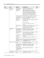
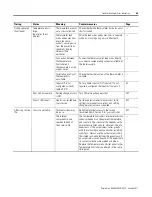
Error Displays
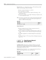
When an error occurs, the error contents are shown on the controller’s No. 1
or No. 2 display.
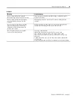
This section describes how to check error codes on the display, and the actions
to be taken to remedy the problems.
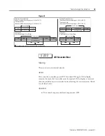
Input Error
Meaning
The input value has exceeded the control range (refer to Note).
Note:
Control Range
Resistance thermometer (RTD), thermocouple input:
–
Temperature setting Lower-Limit
−
20
°
C to temperature setting
Upper-Limit + 20
°
C (Temperature setting Lower-Limit
−
40
°
F to
temperature setting Upper-Limit +40
°
F)
–
Analog input:
−
5% to +105% of scaling range
Action
Check the wiring of inputs for incorrect wiring polarity for improper or
incorrect connections, and short-circuits and check the Input Type.
If no abnormality is found in the wiring and Input Type, turn the controller
power OFF then back ON again.
If the display remains the same, the Controller must be replaced. If the display
is restored, then the probable cause is electrical noise affecting the control
system. Check for electrical noise. Reroute sensor wires away from high
sources of electrical noise. Use shielded sensor wire and ground the shield at
one end.
Note:
With an RTD type input a break in the A, B, or B
1
line is regarded by
the controller as a disconnection.
s.err
Summary of Contents for Allen-Bradley 900-TC16
Page 1: ...USER MANUAL Bulletin 900 TC8 900 TC16 900 TC32 Series B Temperature Controllers...
Page 2: ...2...
Page 72: ...Publication 900 UM007D EN E January 2011 3 2 Configuration Basic Operation Figure 3 3 900 TC32...
Page 136: ...Publication 900 UM007D EN E January 2011 3 66 Configuration Basic Operation Notes...
Page 340: ...Publication 900 UM007D EN E January 2011 5 112 Parameter Functions Definitions Notes...
Page 350: ...Publication 900 UM007D EN E January 2011 6 10 Troubleshooting Error Indication Notes...
Page 406: ...Publication 900 UM007D EN E January 2011 D 8 Glossary Notes...


