Publication 900-UM007D-EN-E -January 2011
C-18
Calibration
Checking Indication
Accuracy
•
After calibrating input, make sure to check indication accuracy to make
sure that the Bulletin 900 Controller has been correctly calibrated.
•
Operate the Bulletin 900 Controller in the PV/SP monitor mode.
•
Check the indication accuracy at the Upper- and Lower-Limits and
mid-point.
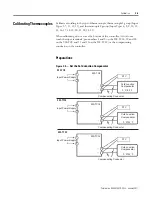
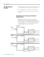
Checking Accuracy of a Thermocouple or Non-Contact
Temperature Sensor
•
Preparation:
The following figure shows the required device
connection. Make sure that the Bulletin 900 Controller and cold
junction compensator are connected by a compensating conductor for
the thermocouple that is to be used during actual operation. For the
non-contact temperature sensor, connect a K thermocouple, and
configured the Input Type to the K thermocouple.
Figure C.36
Cold Junction Compensator
Input Power Supply
Compensation Conductor
900-TC8
1
2
19
20
-
+
STV
Cold Junction Compensator
Input Power Supply
Compensation Conductor
900-TC16
9
10
4
5
-
+
STV
Cold Junction Compensator
Input Power Supply
Compensation Conductor
900-TC32
1
2
11
12
-
+
STV
900-TC8
900-TC16
900-TC32
Summary of Contents for Allen-Bradley 900-TC16
Page 1: ...USER MANUAL Bulletin 900 TC8 900 TC16 900 TC32 Series B Temperature Controllers...
Page 2: ...2...
Page 72: ...Publication 900 UM007D EN E January 2011 3 2 Configuration Basic Operation Figure 3 3 900 TC32...
Page 136: ...Publication 900 UM007D EN E January 2011 3 66 Configuration Basic Operation Notes...
Page 340: ...Publication 900 UM007D EN E January 2011 5 112 Parameter Functions Definitions Notes...
Page 350: ...Publication 900 UM007D EN E January 2011 6 10 Troubleshooting Error Indication Notes...
Page 406: ...Publication 900 UM007D EN E January 2011 D 8 Glossary Notes...


