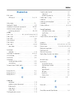
Index
Numerics
2PID control
2PID control . . . . . . . . . . . . . . . . . . . . . . . . . . . . . . 3-16, 3-25
A
Abbreviations . . . . . . . . . . . . . . . . . . . . . . . . . . . . . . . . . . . . P-i
Additional PV display . . . . . . . . . . . . . . . . . . . . . . . . . . . . . . 5-78
Adjustment level parameter operation list . . . . . . . . . . . B-2, B-3
Advanced function setting level . . . . . . . . . . . . . . . . . . . . . . 3-6
parameter operation list . . . . . . . . . . . . . . . . . . . . . . B-9, B-11
Alarms
Alarm 1 type . . . . . . . . . . . . . . . 5-59, 5-61-62, 5-64-66, 5-68, 5-73
Alarm 2 type . . . . . . . . . . . . . . . . . . . . . . . . . . . . . 5-59, 5-63, 5-73
Alarm delays . . . . . . . . . . . . . . . . . . . . . . . . . . . . . . . . . . . . . 4-45
Alarm hysteresis . . . . . . . . . . . . . . . . . . . . . . . . . . . . . . . . . . 4-8
Alarm outputs . . . . . . . . . . . . . . . . . . . . . . . . . . . . . . . . . . . . 3-42
Alarm value 1 . . . . . . . . . . . . . . . . . . . . . . . . . . . . . . . . . . 5-16-18
alarm delays . . . . . . . . . . . . . . . . . . . . . . . . . . . . . . . . . . 4-44
Analog input
calibration . . . . . . . . . . . . . . . . . . . . . . . . . . . . . . . . . . . . C-14
Analog input (voltage input) . . . . . . . . . . . . . . . . . . . . . 4-10, 5-52
AT (Autotuning) . . . . . . . . . . . . . . . . . . . . . . . . . . . . . . . . . . 5-22
Auto control . . . . . . . . . . . . . . . . . . . . . . . . . . . . . . . . . . . . . 4-23
Auto/manual
example operating procedure . . . . . . . . . . . . . . . . . . . . . 4-59
select addition . . . . . . . . . . . . . . . . . . . . . . . . . . . . . . . . . 4-56
Automatic return of display mode . . . . . . . . . . . . . . . . . . . . 5-79
B
Bulletin 900-TC8 . . . . . . . . . . . . . . . . . . . . . . . . . . . . . . . . . P-ii
Bulletin 900-TC16 . . . . . . . . . . . . . . . . . . . . . . . . . . . . . . . . P-ii
Bulletin 900-T32 . . . . . . . . . . . . . . . . . . . . . . . . . . . . . . . . . . P-ii
C
Calibration
analog input . . . . . . . . . . . . . . . . . . . . . . . . . . . . . . . . . . C-10
platinum resistance thermometer . . . . . . . . . . . . . . . . . . C-12
thermocouples. . . . . . . . . . . . . . . . . . . . . . . . . . . . . . . . . C-5
current input . . . . . . . . . . . . . . . . . . . . . . . . . . . . . . . . . . C-14
voltage input . . . . . . . . . . . . . . . . . . . . . . . . . . . . . . . . . . C-16
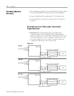
Checking indication accuracy . . . . . . . . . . . . . . . . . . . . . . . . C-18
Communications function . . . . . . . . . . . . . . . . . . . . . . . . . . . 3-8
setting level. . . . . . . . . . . . . . . . . . . . . . . . . . . . . . . . . . . 3-6
parameter operation list . . . . . . . . . . . . . . . . . . . . . . . . . B-14
Control outputs - wiring . . . . . . . . . . . . . . . . . . . . . . . . . . . . 2-23
Controllers. . . . . . . . . . . . . . . . . . . . . . . . . . . . . . . . . . . . . . . P-ii
Controllers with Analog Input . . . . . . . . . . . . . . . . . . . . . . . C-14
Conventions . . . . . . . . . . . . . . . . . . . . . . . . . . . . . . . . . . . . . P-i
Cooling coefficient . . . . . . . . . . . . . . . . . . . . . . . . . . . . . 4-15, 5-36
Current Transformer
calculating detection current. . . . . . . . . . . . . . . . . . . . . . 3-50
specifications . . . . . . . . . . . . . . . . . . . . . . . . . . . . . . . . . A-7
installing . . . . . . . . . . . . . . . . . . . . . . . . . . . . . . . . . . . . . 3-48
Current Value Exceeds (error display) . . . . . . . . . . . . . . . . . 6-4
D
Dead band . . . . . . . . . . . . . . . . . . . . . . . . . . . . . . . . . . . . . . . 5-37
Decimal point . . . . . . . . . . . . . . . . . . 5-33, 5-42, 5-49, 5-52, 5-54
Derivative time . . . . . . . . . . . . . . . . . . 3-30, 3-39, 5-22, 5-25, 5-35
Dimensions, approximate . . . . . . . . . . . . . . . . . . . . . . . . . . . . A-7
Detection current. . . . . . . . . . . . . . . . . . . . . . . . . . . . . . . . . . 3-50
Direct/reverse operation . . . . . . . . . . . . . . . . . . . . . . . . . . . . 5-58
Display Range Exceeded (error display) . . . . . . . . . . . . . . . 6-2
E
Ehanced Features . . . . . . . . . . . . . . . . . . . . . . . . . . . . . . . . . P-ii
Error displays
Current Value Exceeds . . . . . . . . . . . . . . . . . . . . . . . . . . 6-4
Display Range Exceeded . . . . . . . . . . . . . . . . . . . . . . . . 6-2
HB Error . . . . . . . . . . . . . . . . . . . . . . . . . . . . . . . . . . . . . 6-3
Heater Burnout . . . . . . . . . . . . . . . . . . . . . . . . . . . . . . . . 6-5
HS Alarm . . . . . . . . . . . . . . . . . . . . . . . . . . . . . . . . . . . . 6-5
Input Error . . . . . . . . . . . . . . . . . . . . . . . . . . . . . . . . . . . 6-1
Memory Error . . . . . . . . . . . . . . . . . . . . . . . . . . . . . . . . . 6-4
Event Input . . . . . . . . . . . . . . . . . . . . . . . . . . . . . . . . . . . 4-16
F
Front panel . . . . . . . . . . . . . . . . . . . . . . . . . . . . . . . . . . . . . . 1-11
G
General/Environmental Specifications . . . . . . . . . . . . . . . . . A-4
Summary of Contents for Allen-Bradley 900-TC16
Page 1: ...USER MANUAL Bulletin 900 TC8 900 TC16 900 TC32 Series B Temperature Controllers...
Page 2: ...2...
Page 72: ...Publication 900 UM007D EN E January 2011 3 2 Configuration Basic Operation Figure 3 3 900 TC32...
Page 136: ...Publication 900 UM007D EN E January 2011 3 66 Configuration Basic Operation Notes...
Page 340: ...Publication 900 UM007D EN E January 2011 5 112 Parameter Functions Definitions Notes...
Page 350: ...Publication 900 UM007D EN E January 2011 6 10 Troubleshooting Error Indication Notes...
Page 406: ...Publication 900 UM007D EN E January 2011 D 8 Glossary Notes...


