Publication 900-UM007D-EN-E - January 2011
2-4
Preparations
•
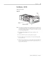
Horizontal group-mounting of two or more temperature controllers, or
mounting temperature controllers above each other may cause heat to
build up inside the temperature controllers. This will shorten their
service life. When mounting temperature controllers like this, consider
forced cooling measures, such as a cooling fan.
•
If forced air cooling is used, limit cooling to the terminal block. Rapid
variation or transients in temperature at the terminal block may result in
a measurement error.
System Wiring and Installation Guidelines
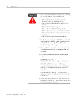
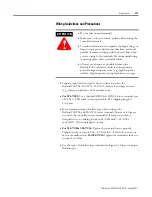
ATTENTION
!
Risk of Electrical Shock
•
Devices are Open Type, Listed Process Control
Equipment and must be mounted in an enclosure.
•
More than one disconnect switch may be required to
de-energize the equipment before servicing.
•
Signal inputs are SELV, limited energy.
•
To reduce risk of fire or electrical shock, do not
interconnect the outputs of different Class 2 circuits.
•
Disconnect all power (including field device) before
installing and/or servicing.
•
Do not touch the controller’s wiring terminals while
the power is ON. Doing so may cause an electric
shock.
Summary of Contents for Allen-Bradley 900-TC16
Page 1: ...USER MANUAL Bulletin 900 TC8 900 TC16 900 TC32 Series B Temperature Controllers...
Page 2: ...2...
Page 72: ...Publication 900 UM007D EN E January 2011 3 2 Configuration Basic Operation Figure 3 3 900 TC32...
Page 136: ...Publication 900 UM007D EN E January 2011 3 66 Configuration Basic Operation Notes...
Page 340: ...Publication 900 UM007D EN E January 2011 5 112 Parameter Functions Definitions Notes...
Page 350: ...Publication 900 UM007D EN E January 2011 6 10 Troubleshooting Error Indication Notes...
Page 406: ...Publication 900 UM007D EN E January 2011 D 8 Glossary Notes...


