Publication 900-UM007D-EN-E - January 2011
Preparations
2-31
Hardware Installation
EXAMPLE
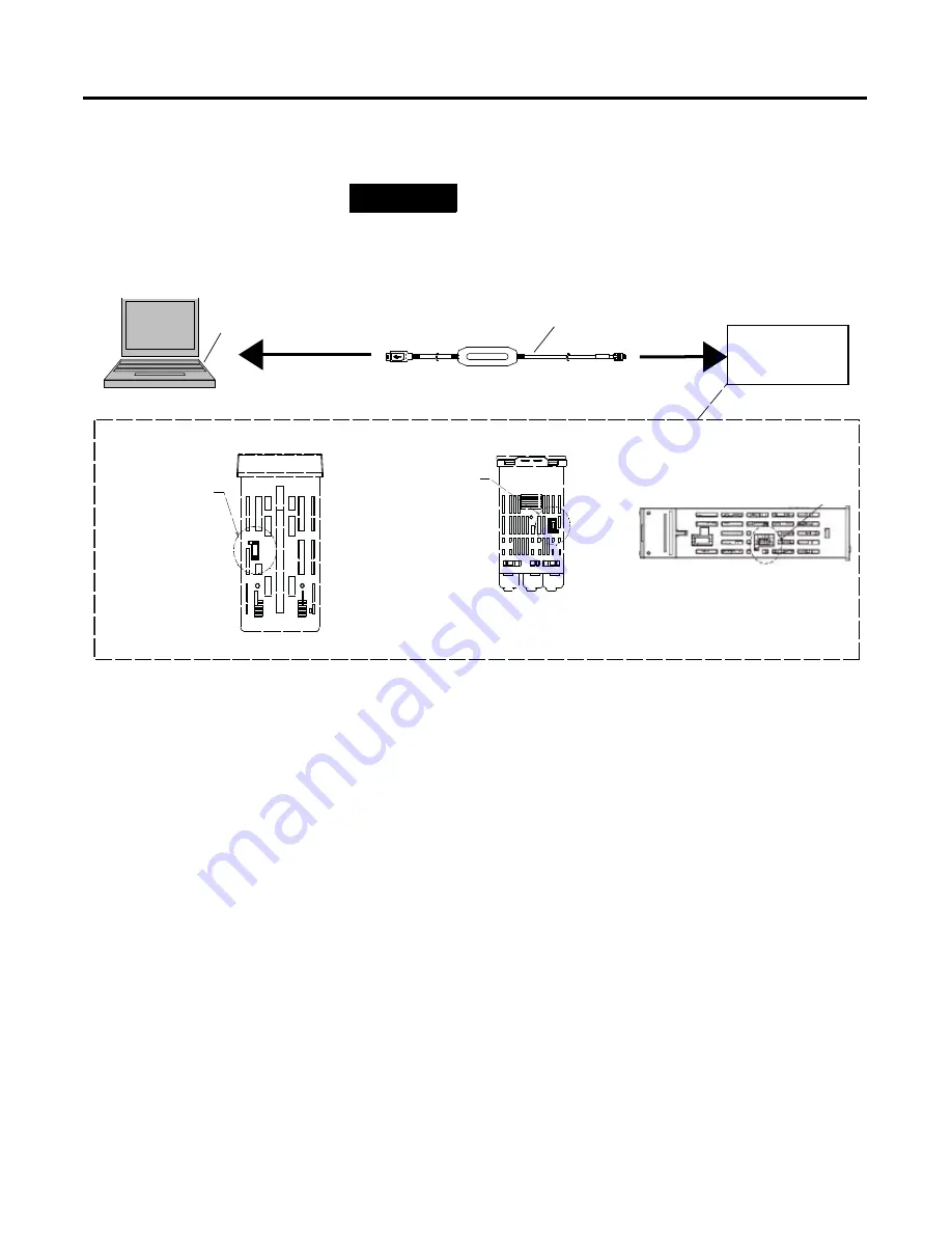
Figure 2.31 — Temperature Controller Connection Method
1.
Turn ON the power to the Temperature Controller.
Note:
If the cable is
connected when the power to the Temperature Controller is OFF,
power will be supplied from the personal computer and impose a load
on the internal circuits of the Temperature Controller.
2.
Connect the cable.
Connect the personal computer’s USB port with the Support Software
port on the Temperature Controller using the Cable.
Note:
Hold the
connector when inserting or disconnecting the cable.
3.
Install the driver.
Note:
The driver is available free of charge from the Bulletin 900 Temperature
Controller Website:
www.ab.com/industrialcontrols/products/relays_timers_and_temp_
controllers/single_loop_temp_heater_controllers/900tc.html. Refer to
the menu on the right and click on Get Software for Serial Conversion
Cable.
Install the driver to enable the cable to be used with the personal
computer.
➊
➊
900 BuilterLite version 1.1 for Series A controllers and Version 1.2 for Series B controllers
Personal Computer
USB Port
900-CPOEM1 Cable
Communications
Port for Support
Software
900-TC8
Communications
Port for Support
Software
900-TC32
Communications Port
for Support Software
900-TC16
Bottom View of Temperature Controllers
Communications Port
for Support Software
Summary of Contents for Allen-Bradley 900-TC16
Page 1: ...USER MANUAL Bulletin 900 TC8 900 TC16 900 TC32 Series B Temperature Controllers...
Page 2: ...2...
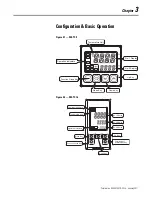
Page 72: ...Publication 900 UM007D EN E January 2011 3 2 Configuration Basic Operation Figure 3 3 900 TC32...
Page 136: ...Publication 900 UM007D EN E January 2011 3 66 Configuration Basic Operation Notes...
Page 340: ...Publication 900 UM007D EN E January 2011 5 112 Parameter Functions Definitions Notes...
Page 350: ...Publication 900 UM007D EN E January 2011 6 10 Troubleshooting Error Indication Notes...
Page 406: ...Publication 900 UM007D EN E January 2011 D 8 Glossary Notes...

