250
Rockwell Automation Publication 193-UM015D-EN-P - February 2015
Chapter 6
Protective Trip and Warning Functions
•
Any relay outputs configured as a Control Relay open
•
Any relay outputs configured as a Trip Alarm close
•
Any relay outputs configured as a Normal Relay are placed in their
Protection Fault state (if so programmed)
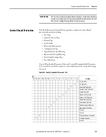
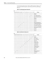
Start Inhibit Protection
This protective function allows you to limit the number of starts in a given time
period and limit the operating hours for an electric motor. A start is defined as
the E300 Electronic Overload Relay sensing a transition in current from 0 A to
30% of the minimum FLA rating of the device. The Blocked Start protective
function is set by Starts Per Hour (Parameter 205) and/or Starts Interval
(Parameter 206).
Blocked Start Trip
The E300 Electronic Overload Relay trips with a blocked start trip indication if:
•
No trip currently exists
•
Blocked Start Trip is enabled
•
The number of starts within the past hour equals the value set in Starts Per
Hour (Parameter 205)
•
The time between starts is less than the value set in Starts Interval
(Parameter 206)
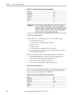
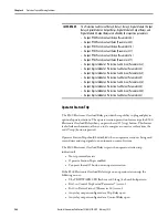
IMPORTANT
The Protection Fault State of Relay 0, Relay 1, Relay 2, Digital Module 1 Output
Relays, Digital Module 2 Output Relays, Digital Module 3 Output Relays, and
Digital Module 4 Output Relays are defined by the respective parameters:
•
Output PT00 Protection Fault Action (Parameter 304)
•
Output PT00 Protection Fault Value (Parameter 305)
•
Output PT01 Protection Fault Action (Parameter 310)
•
Output PT01 Protection Fault Value (Parameter 311)
•
Output PT02 Protection Fault Action (Parameter 316)
•
Output PT02 Protection Fault Value (Parameter 317)
•
Output Digital Module 1 Protection Fault Action (Parameter 322)
•
Output Digital Module 1 Protection Fault Value (Parameter 323)
•
Output Digital Module 2 Protection Fault Action (Parameter 328)
•
Output Digital Module 2 Protection Fault Value (Parameter 329)
•
Output Digital Module 3 Protection Fault Action (Parameter 334)
•
Output Digital Module 3 Protection Fault Value (Parameter 335)
•
Output Digital Module 4 Protection Fault Action (Parameter 340)
•
Output Digital Module 4 Protection Fault Value (Parameter 342)
Summary of Contents for Allen-Bradley E300
Page 1: ...E300 Electronic Overload Relay Bul 193 592 User Manual...
Page 128: ...128 Rockwell Automation Publication 193 UM015D EN P February 2015 Chapter 5 Operating Modes...
Page 304: ...304 Rockwell Automation Publication 193 UM015D EN P February 2015 Chapter 7 Commands Notes...
Page 502: ...502 Rockwell Automation Publication193 UM015D EN P November 2013 Appendix B Parameter List...
Page 545: ......


