Rockwell Automation Publication 440G-UM001A-EN-P — November 2013
15
Installation and Wiring
Chapter 3
Setting the Actuator
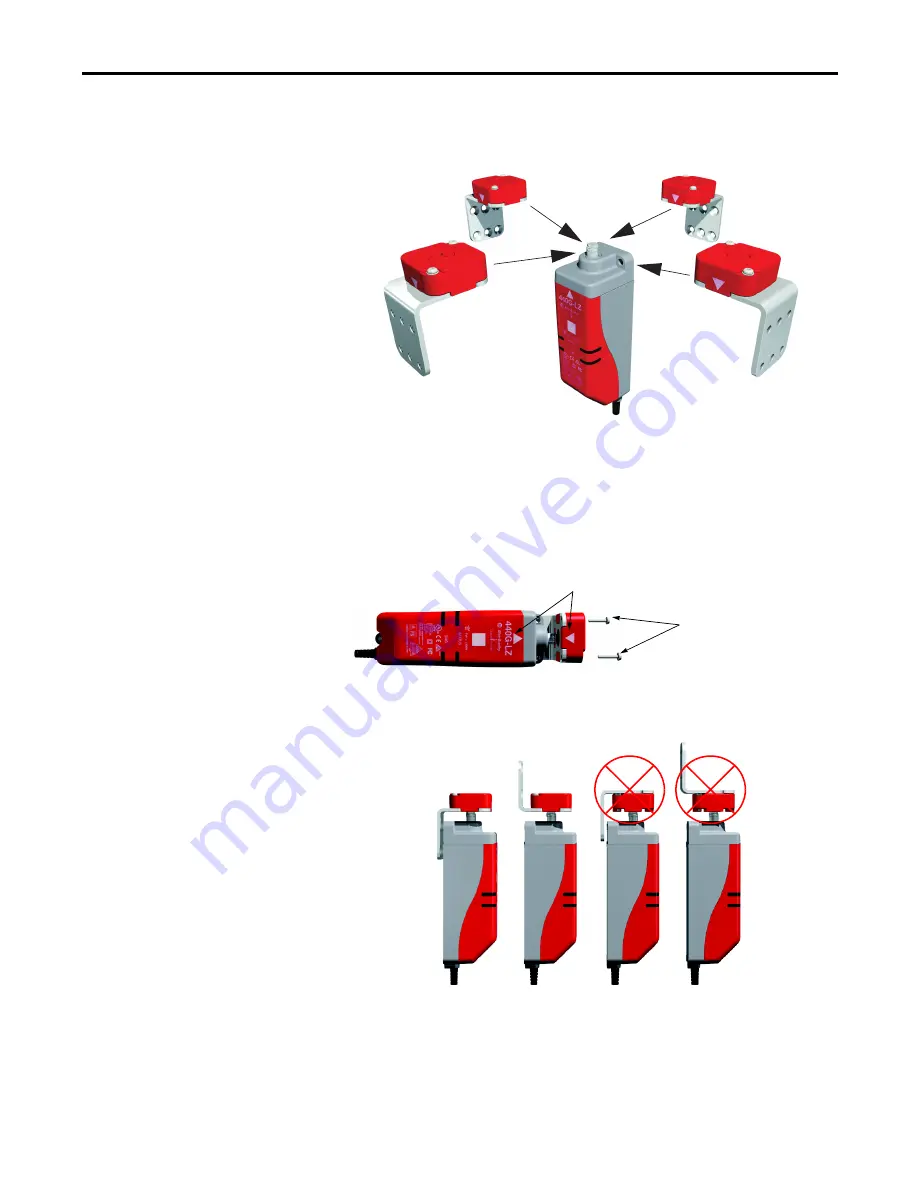
Direction of Approach
The actuator can approach the switch from all four directions.
Ensure the white arrow on the actuator aligns with the white arrow on
the switch body.
The actuator must be fitted to the actuator mounting bracket in such a
manner that the white alignment triangles marked on both the actuator
and switch body are in the installed position.
Ensure the locking bolt enters the actuator mounting bracket first.
Align the white triangles.
0.4 Nm
2 x T10 Torx screws
Summary of Contents for Allen-Bradley Guardmaster 440G-LZ
Page 1: ...Guardmaster 440G LZ Guard Locking Switch User Manual ...
Page 39: ......


