Rockwell Automation Publication 440R-UM014D-EN-P - December 2019
39
Troubleshooting
Chapter 8
Output Is Energized but
Contactors Are Off (Step 7)
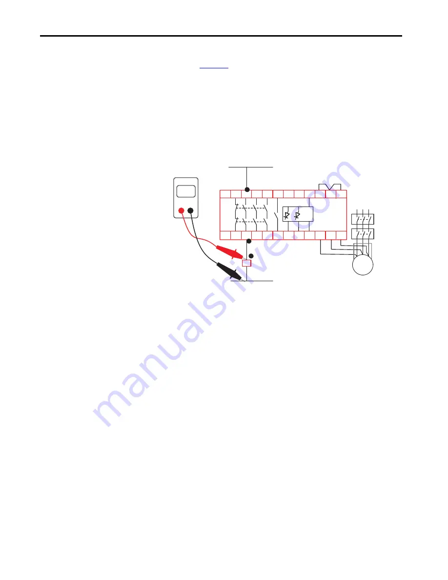
Measure the voltage at the contactors. An example of the measurement points
is shown in
. If voltage is not present at point 1, measure the voltage at
points 2 and 3 in the circuit.
If voltage is not present at point 3, then following the wiring back to the source
to detect the cause (blown fuse, tripled circuit breaker, open wire connection).
If the voltage is present at point 3 but is not available at point 2, check the
wiring at the relay terminals. If the wiring is okay, then you must replace the
MSR55P safety relay.
Figure 24 - Check the Output Wiring Voltage
Output Is On While Motor
Still Turns (Step 8)
Reduce setting of V
m
if necessary to minimum. If the outputs are still enabled, a
wiring problem on the measuring wires could be the reason (short circuit on
terminals L2/L3 to L1) or the motor generates only a low voltage. Check
connection of measuring inputs to motor winding according to the connection
examples.
Increase the delay time t
s
setting to allow the motor more time to spin to a stop.
Vs
Vs
L1 L2 L3
V AC or
V DC
DMM
K1
A2
X1 X2
L3
L2
L1
X3
34 44
A1
A3
33
23
11
24
12
ON ERR A4
54
43 53
M
3~
1
2
3


