22
Rockwell Automation Publication 440G-UM001B-EN-P - May 2016
Chapter 3
Installation and Wiring
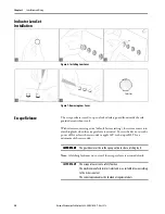
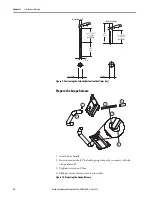
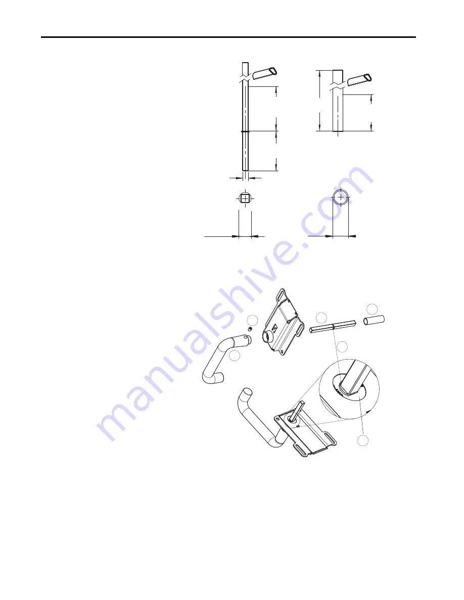
Figure 9 - Shortening the Extended Actuation Shaft [mm (in.)]
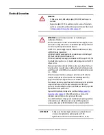
Prepare the Escape Release
1. Attach door handle
2. Insert actuation shaft. The locking ring A must be in contact with the
escape release B.
3. Tighten setscrew to 2 Nm
4. Slide protective sleeve over actuation shaft
Figure 10 - Preparing the Escape Release
55.5
(2.19)
D + 13.5 (0.53)
(+ 4 (0.16)
182
(7.16)
D + 3 (0.12)
(+ 4 (0.16)
8
(0.32)
Ø
11.2 (0.44)
Ø
14 (0.55)
Actuation shaft
Protective sleeve
per Plate)
per Plate)
1
3
2
4
A
B


