30
Rockwell Automation Publication 440G-UM001B-EN-P - May 2016
Chapter 4
Description of Operation
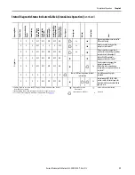
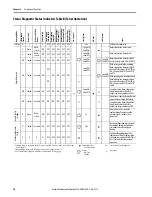
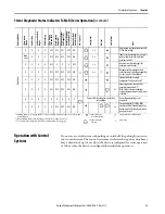
Status Diagnostic Status Indicators Table B (Series Operation)
Self-test
X
X
X
X
OFF OFF OFF OFF
OFF
5 Hz
Self-test after power-up
X
Open
Not in-
serted
OFF
OFF OFF OFF OFF
OFF
Long OFF
Short ON
Normal operation, door is open
X
Closed
Not in-
serted
OFF
OFF OFF OFF OFF
OFF
Long ON,
short OFF
Normal operation, door closed
OFF
Closed In-serted OFF
OFF
ON
ON
OFF
OFF
Long ON,
Short OFF
Long ON,
Short OFF
Normal operation, door closed, bolt
inserted safety inputs FI1A/FI1B OFF
ON
Closed In-serted OFF
OFF
ON
ON
OFF
OFF
Long ON,
short OFF
Long ON,
Short OFF
With active guard lock monitoring:
Normal operation, door closed, bolt
inserted. Safety inputs FI1A/FI1B are
ON. Safety outputs FO1A and FO1B
are OFF.
ON
With inactive guard lock monitoring:
Normal operation, door closed, bolt
inserted. Safety inputs FI1A/FI1B are
ON. Safety outputs FO1A and FO1B
are ON.
OFF
Closed In-serted ON
OFF
ON
ON
ON
OFF
Long ON,
Short OFF
Series Operation: Normal operation,
door closed and locked. Safety
outputs on the previous device OFF.
ON
Closed In-serted ON
ON
ON
ON
ON
OFF
Operation as separate device: Normal
operation, door closed and locked.
Series Operation: Normal operation,
door closed and locked. Safety
outputs on the previous device ON.
X
Open
Not in-
serted
OFF
OFF OFF OFF OFF
OFF
3 x
Door is open: unit is ready for
configuration of another handle
assembly (only 3 minutes after
power-up).
X
Closed In-serted ON
OFF OFF OFF OFF
OFF
2 Hz
Handle configuration tip: to prevent
interruption during configuration,
close door and switch on guard
locking.
X
X
X
X
OFF OFF OFF OFF
OFF
Position acknowledgement after
completion of handle configuration.
Cycle power or apply 24V to RST for at
least 3 seconds to resume normal
operation.
* Latching fault; to reset, use the RST input or briefly disconnect the device from the
power supply.
** Non-latching fault; open safety guard and close it again to reset.
***See Troubleshooting and Assistance in Appendix A on
.
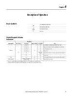
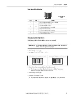
Status indicator
not illuminated
status indicator illuminated
Status
indicato
r flashes
x
Any state
Op
er
at
in
g
Mo
de
Sa
fe
ty
Inp
uts
FIA
and
Door
Po
sit
io
n
Po
siti
on
of
the
Bo
lt
To
ng
ue
Guard
Locking
Sa
fe
ty
O
ut
pu
ts
FO1A
and
FO1B
Door
Mount
ing
Ou
tp
ut
(O
D)
Monitoring
Ou
tput
Bolt
To
ngue
(O
T)
Gu
ard
Lo
ck
in
g
M
on
-
itor
in
g
Ou
tput
(O
L)
Diagnos
tics
Moni
-
tori
ng
O
utp
ut
(O
I)
Po
w
er
(gr
een)
Sta
te
(g
reen)
DI
A
(red
)
Loc
k (y
ello
w
)
Sta
te
No
rmal
O
pera
tion
Ha
ndl
e C
on
fig
.
Standby
Ha
ndl
e C
on
fig
ur
atio
n
Se
t-up


