Rockwell Automation Publication 440G-UM001B-EN-P - May 2016
43
Chapter
5
Wiring Examples
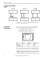
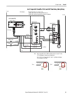
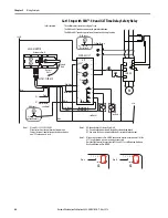
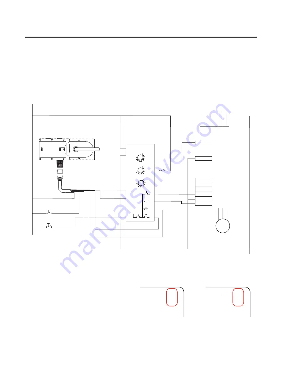
Cat 1 Stop with Kinetix® 300 and GLT Time Delay Safety Relay
A1
A2
L12
S54
L11
0
1
2
3
4
5
6
7
8
9
1
2
3
4
5
8
10
9
S21
S11
B2
6
7
0
1
2
3
4
5
6
7
8
9
S22
S12
Y32
S44
A1
14
24
51
L61
GLT
889M-F19RM-X
24V DC
0V COM
440R-GL2S2T
442G-MAB PTR
8
7
6
5
4
3
2
1
X3
IMM
0V
UA
IMP1
IMP2
8
7
6
5
4
3
2
1
X3
IMM
IMP
*
0V
UA
+24V DC
COM
1
2
3
4
5
6
Kinetix 300
L1
L3
M
I/O
L2
3
4
10
IN_x_COM
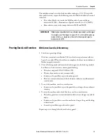
In this example
The unlock request initiates a category 1 stop.
The MAB and GLT provide a time delayed guard lock function.
The MAB and GLT provide a prevention of unexpected start-up function.
Hardware Rev. B
Safe Torque-off (STO)
Connector with
D Wiring Header
- see Note 2
Time
Blue
LOGIC*
(IOD) Connector
Brown
Range
Unlock Request
White
Reset/Lock
Green/Black
Red/Blue
Unlock Cmd A
Digital Input
Unlock Cmd B
Violet
Gray/Brown
Note 1: When using a Hardware Rev. A MAB, connect the violet wire to terminal
51 of the GLT. The gray/brown wire must be remain unconnected.
Note that the terminal designations for X3.6 and X3.7 are different on
Hardware Rev. A and Hardware Rev. B MAB.
Gray/Pink
- see Note 1
MAB Reset/Lock
Safety Input 1
Status
Safety Input 2
Safety Common
Note 2: The digital input configured for Abort Index in MotionView software, must be
active-high when the safety function is requested. Digital input common
(IN_x_COM) must be used in this signal activation/de-activation transition.
Rev. A
Rev. B

