Rockwell Automation Publication 440G-UM001B-EN-P - May 2016
15
Chapter
3
Installation and Wiring
General Considerations
Installation must be in accordance with the present manual and must be
performed by qualified personnel exclusively. The Access Box guard locking
switch system is intended to be part of the safety-related control system of a
machine. Before installation, a thorough risk assessment must be performed to
determine whether the specifications (see page
) of this device are suitable
for all foreseeable operational and environmental characteristics of the
application.
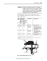
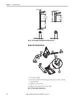
Use appropriate screws, bolts, or nuts that are fitted by tools to mount the lock
module and handle assembly to avoid tampering. Do not over-torque the
mounting hardware.
Handle Configuration
The unique-coded handle assembly must be assigned to the locking module
before the system is functional.
During configuration of the handle, the safety outputs are switched off.
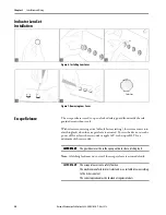
• Insert bolt tongue in the locking module.
• Apply operating voltage (U
A
and U
B
).
• The State status indicator flashes (5 Hz) as the device performs a self-test
(up to 8 seconds).
• Programming begins when the State status indicator flashes (1 Hz).
After approximately 60 seconds, the State status indicator turns off.
• To complete the configuration, switch off the operating voltage (UB)
for a minimum of 3 seconds or apply 24V to the input RST for a
minimum of 3 seconds.
IMPORTANT
The locking module disables the code for the previous handle assembly if
configuration is conducted for a new handle assembly. A disabled handle
assembly can be configured again only after a third handle assembly has
been configured.


