Rockwell Automation Publication 2198-RM003A-EN-P - February 2020
59
Dimensions, Cables, and Wiring
Chapter 4
.
The
shows the pin orientation for 15-pin motor feedback connector.
Figure 28 - Pin Orientation for 15-pin Motor Feedback (MF) Connector
Factory-made cables with premolded connectors are designed to minimize
electromagnetic interference (EMI). We recommend factory-made cables (over
hand-built cables) to improve system performance. Feedback cables with
premolded connectors that are used with the Kinetix MP motors work with both
the Ultra3000 and Kinetix 5100 drives, with no modification. Feedback cable
with flying leads can be connected to the Kinetix 5100 drive MFB port with the
connector kit, cat. no. 2198-K51CK-D15M.
For further information, see the Motion Control Accessories section in the
Kinetix Motion Control Selection Guide, publication
, the bill of
materials (BOM) configuration tool within Motion Analyzer, or
ProposalWorks™ from Rockwell Automation.
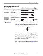
Table 52 - Feedback Cable Descriptions (continuous-flex cable)
Standard Cable Cat. No.
Description
Cable Configuration
Motor/Actuator
Connector
Motor/Acutator End Drive End
2090-CFBM7DF-CDAF
xx
• Drive-end flying leads (DF)
• High-resolution or incremental applications (CD)
SpeedTec DIN (M7)
2090-CFBM7DF-CEAF
xx
• Drive-end flying leads (DF)
• High-resolution or resolver applications (CE)
2090-CFBM7DD-CEAF
xx
• Drive-end 15-pin connector (DD)
• High-resolution or resolver applications (CE)
2090-CFBM7E7-CDAF
xx
• Drive-end (male) connector, extension (E7)
(1)
• Motor-end SpeedTec DIN cable plug (M7)
2090-CFBM7E7-CEAF
xx
2090-CFBM4DF-CDAF
xx
• Drive-end flying leads
• High-resolution or incremental applications
Threaded DIN (M4)
(1) SpeedTec DIN connector (motor end) and male connector for extending SpeedTec or threaded DIN cable. See the SpeedTec DIN Continuous-flex Extension Cables in the Kinetix Motion Accessories
Technical Data, publication
Pin 11
Pin 6
Pin 15
Pin 1
Pin 10
Pin 5


