Publication 2094-UM001A-EN-P — September 2006
Configure and Startup the Kinetix 6000 Drive System
123
Node Addressing Example 2
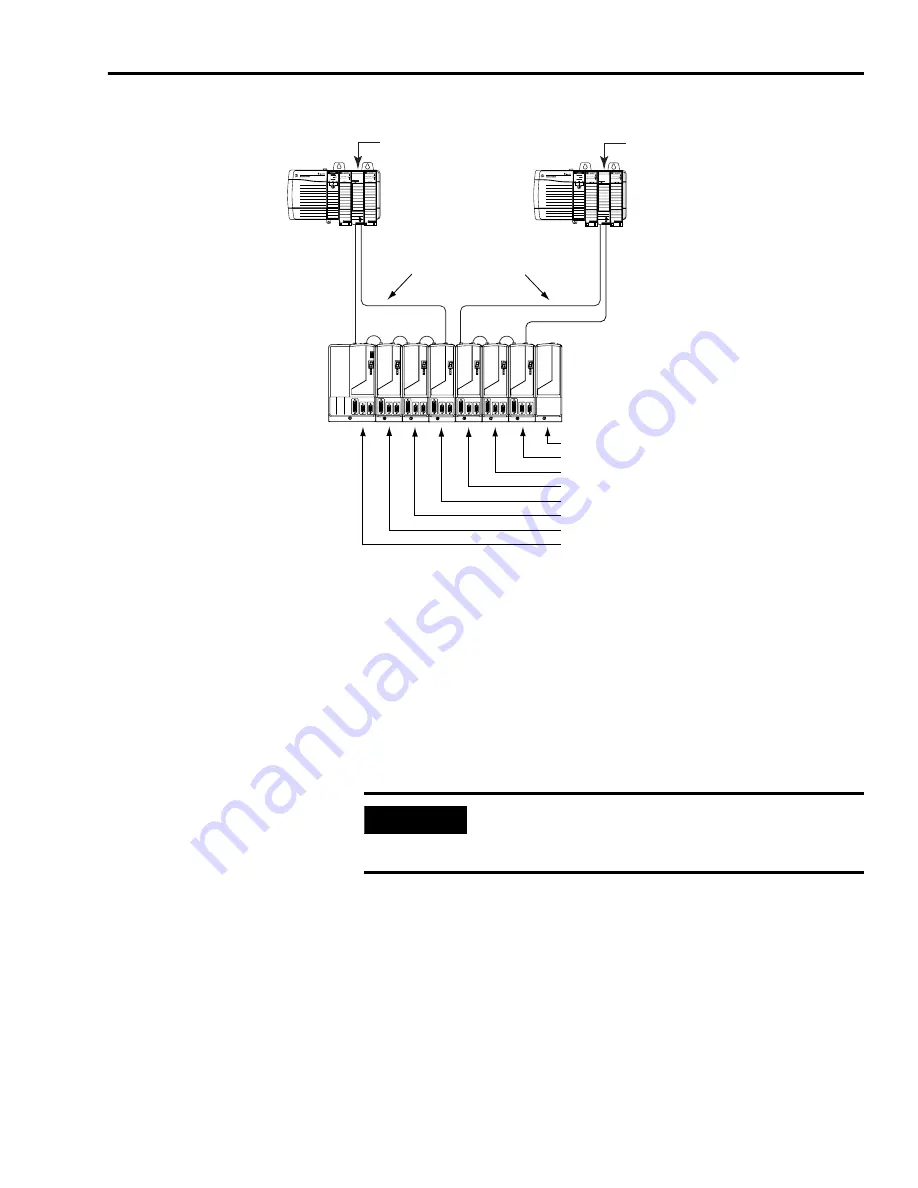
In the example above, SERCOS interface module 1 controls axes
1 to 4 and module 2 controls axes 5 to 7. The slot filler module is
assigned a node address, but does not use it.
You can mount the two SERCOS interface modules in two separate
ControlLogix chassis (as shown above) or you can mount them in the
same chassis.
Utilizing two SERCOS interface modules to control axes from a single
Kinetix 6000 power rail allows you to reduce the cycle times.
SERCOS interface
TM
Tx (rear)
Rx (front)
OK
CP
SERCOS interface
TM
Tx (rear)
Rx (front)
OK
CP
08 = Slot Filler node address
07 = AM (axis 7) node address
06 = AM (axis 6) node address
05 = AM (axis 5) node address
04 = AM (axis 4) node address
03 = AM (axis 3) node address
02 = AM (axis 2) node address
01 = IAM (axis 1) base node address
ControlLogix Chassis
SERCOS Fiber-Optic rings
1756-M
xx
SE SERCOS
interface Module 1
Kinetix 6000
(8-axis power rail)
Receive
Receive
Transmit
Transmit
Transmit
Receive
ControlLogix Chassis
1756-M
xx
SE SERCOS
interface Module 2
Transmit
Receive
IMPORTANT
Slot Filler modules must be used to fill any unoccupied slot on
the power rail. However, the slot fillers may also be removed
and replaced by an axis or shunt module in the future.
Summary of Contents for Allen-Bradley Kinetix 6000
Page 8: ...Publication 2094 UM001A EN P September 2006 8 Table of Contents...
Page 18: ...Publication 2094 UM001A EN P September 2006 18 Start...
Page 118: ...Publication 2094 UM001A EN P September 2006 118 Connecting the Kinetix 6000 Drive System...
Page 190: ...Publication 2094 UM001A EN P September 2006 190 Specifications and Dimensions...
Page 265: ...Publication 2094 UM001A EN P September 2006 265 Notes...
Page 266: ...Publication 2094 UM001A EN P September 2006 266 Notes...
Page 267: ...Publication 2094 UM001A EN P September 2006 267 Notes...


