Publication 2094-UM001A-EN-P — September 2006
Configure and Startup the Kinetix 6000 Drive System
135
Apply Power to the
Kinetix 6000 Drive
This procedure assumes that you have wired and configured your
Kinetix 6000 system (with or without the LIM) and your SERCOS
interface module.
Refer to the Line Interface Module Installation Instructions, publication
2094-IN005, when troubleshooting the LIM status indicators, and for
the location of LIM circuit breakers, connectors, and status indicators.
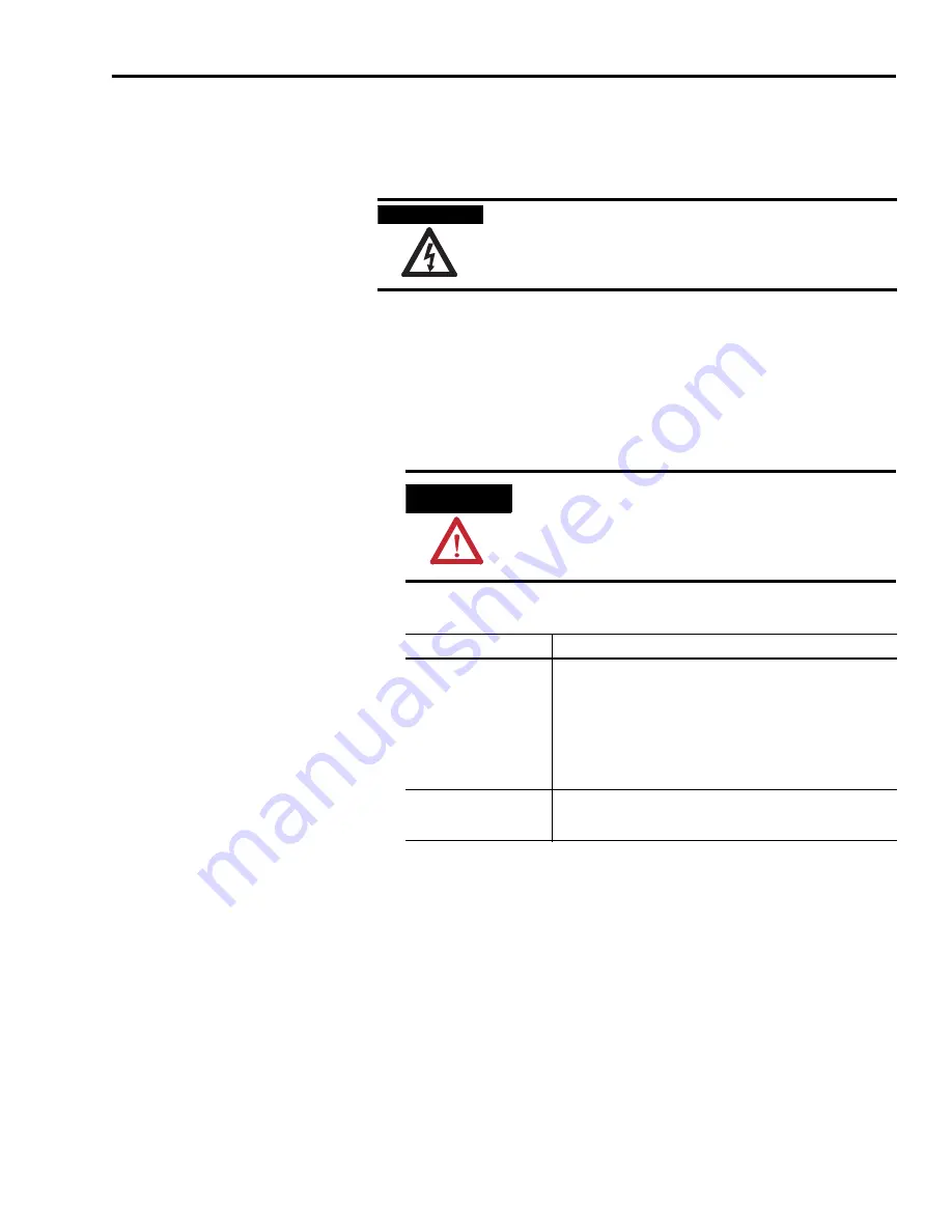
Follow these steps to apply power to the Kinetix 6000 system.
1.
Disconnect the load to the motor.
2.
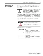
Determine your source of control power.
SHOCK HAZARD
To avoid hazard of electrical shock, perform all mounting and
wiring of IAM, AM, SM, LIM, RBM, or power rail prior to
applying power. Once power is applied, connector terminals
may have voltage present even when not in use.
ATTENTION
To avoid personal injury or damage to equipment,
disconnect the load to the motor. Make sure each motor is
free of all linkages when initially applying power to the
system.
If Your Control Power
Then
Is sourced from a LIM
1. Verify that CB1, CB2, and CB3 are in the OFF position.
2. Apply three-phase input power to the LIM VAC Line connector.
3. Set CB3 to the ON position.
4. Set CB2 to the ON position.
5. Go to main Step 3.
Is not sourced from a LIM
1. Apply (95...264V ac) control power to the IAM (CPD connector).
2. Go to main Step 3.
Summary of Contents for Allen-Bradley Kinetix 6000
Page 8: ...Publication 2094 UM001A EN P September 2006 8 Table of Contents...
Page 18: ...Publication 2094 UM001A EN P September 2006 18 Start...
Page 118: ...Publication 2094 UM001A EN P September 2006 118 Connecting the Kinetix 6000 Drive System...
Page 190: ...Publication 2094 UM001A EN P September 2006 190 Specifications and Dimensions...
Page 265: ...Publication 2094 UM001A EN P September 2006 265 Notes...
Page 266: ...Publication 2094 UM001A EN P September 2006 266 Notes...
Page 267: ...Publication 2094 UM001A EN P September 2006 267 Notes...


