84
Rockwell Automation Publication 2715P-UM001C-EN-P - March 2019
Chapter 5
Install and Replace Components
7.
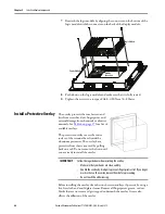
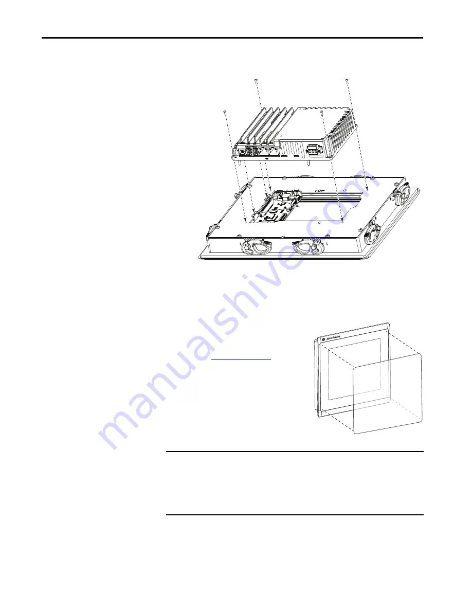
Reattach the logic module by aligning the connector on the bottom of the
logic module with the connector on the back of the display module.
8.
Push down on the logic module and make sure that it is fully seated.
9.
Tighten the screws to a torque of 0.68…0.90 N•m (6…8 lb•in).
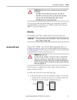
Install a Protective Overlay
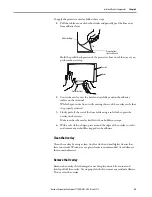
The overlay protects the touch screen and
keys from scratches, dust, fingerprints, and
external damage from chemicals or abrasive
materials. See
for a list of
available overlays.
The protective overlay covers the entire
surface of the terminal bezel inside the
aluminum perimeter. The overlay has a
protective liner that is removed by pulling
back on a tab. Do not remove the liner until
you are ready to install the overlay.
Before installing the overlay, clean the touch screen and keys, if present, by using a
lint-free cloth and a mild glass cleaner. Remove all fingerprints, grease, or dust.
Marks that are not removed get trapped underneath the overlay. Grease also
affects the adhesion of the overlay.
Module
Connectors
Logic Module
Display Module
IMPORTANT
Follow these guidelines when installing the overlay:
• Make sure that your hands are clean and dry.
• Handle the overlay by its edges to prevents fingerprints or lint. If you do get
marks or lint on the overlay, remove them before proceeding.
• Do not touch the adhesive ring.
Summary of Contents for Allen-Bradley PanelView 5510 Series
Page 6: ...6 Rockwell Automation Publication 2715P UM001C EN P March 2019 Table of Contents Notes...
Page 10: ...10 Rockwell Automation Publication 2715P UM001C EN P March 2019 Preface Notes...
Page 108: ...108 Rockwell Automation Publication 2715P UM001C EN P March 2019 Index Notes...
Page 109: ...Rockwell Automation Publication 2715P UM001C EN P March 2019 109 Index Notes...
Page 110: ...110 Rockwell Automation Publication 2715P UM001C EN P March 2019 Index Notes...
Page 111: ......

