background image

44

Rockwell Automation Publication 6000-IN100B-EN-P - October 2020

Chapter 2          Drive Electrical Installation

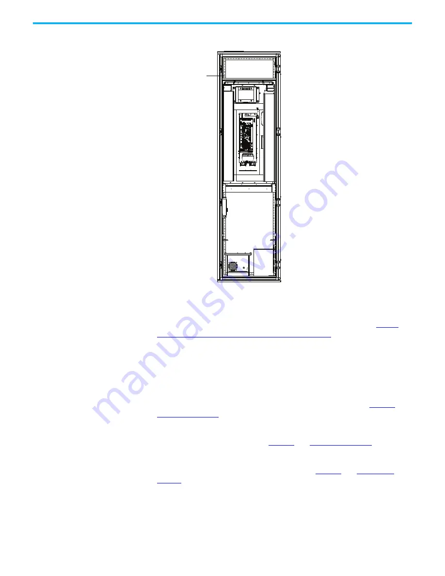
Figure 23 - Terminal Block Strip locations

Connect External Control 
Signal Wiring 

This section summarizes the control signal wiring from the remote DCS/PLC 
or discrete control to the drive. General connections are detailed in 

Power 

Cabling and Control Signal Wiring Details on page 63

. Refer to the Electrical 

Drawings for connection information specific See the drive being installed.

Analog and Digital I/O Overview

Four 4…20 mA analog input signals. One may be used for DCS with rotating 
speed setting and three for backup. For detailed information, see 

Table 14

 and 

Table 15 on page 66

.

Up to four 4…20 mA analog output signals for indication signals such as output 
motor current and frequency. See 

Table 14

 and 

Table 15 on page 66

.

Twelve passive dry contact inputs (internal 24V DC power supply) start/stop 
and reset controls. For detailed information, see 

Table 14

 and 

Table 15 on 

page 66

. These inputs are scalable depending on user requirements. 

Four dry contact outputs from the POD option cards are standard with a 
capacity of 20W for indication. Interposing relays are provided to interfacing 
to power switching devices and fault status information. The quantity is based 
on the options ordered with the drive. The rating of these contacts are 

-A-

VFD1 Terminal 

Block strip

Summary of Contents for Allen-Bradley PowerFlex 6000T

Page 1: ...PowerFlex 6000T Drives Catalog Number 6000T Installation Instructions Original Instructions ...

Page 2: ...ll Automation Inc with respect to use of information circuits equipment or software described in this manual Reproduction of the contents of this manual in whole or in part without written permission of Rockwell Automation Inc is prohibited Throughout this manual when necessary we use notes to make you aware of safety considerations Labels may also be on or inside the equipment to provide specific...

Page 3: ...c Rated Enclosures 16 Install Main Cooling Fans 23 Install Power Modules if applicable 26 External Ducting 30 Air Conditioning Sizing 32 Chapter 2 Drive Electrical Installation Safety and Codes 33 Electrical Drawings 34 Grounding System Requirements 34 Power Cable Insulation Requirements 35 Power Cable Design Considerations 35 Motor Cable Sizing 36 Control Signal Wiring Design Considerations 36 El...

Page 4: ...bles 50 Connect LV Control and Fan Wiring Bundles 52 Connect Ground Bus 52 Complete the Installation 53 Appendix A Pre Commissioning Pre Commissioning Responsibilities 55 Pre Commissioning Checklist 55 Appendix B Torque Requirements Torque Requirements 59 Appendix C General Wire Categories General Wire Categories 61 Appendix D Power Cabling and Control Signal Wiring Details Schematic Diagrams 63 S...

Page 5: ... for installing a PowerFlex 6000T drive It does not include project specific or drive specific topics such as Dimensional Drawings DD and Electrical Drawings ED that are generated for each customer s order Spare parts lists compiled for each customer s order Drive specific technical specifications For additional product detail or information relating to PowerFlex 6000T drives see the publications ...

Page 6: ...he cabinet door and verify the absence of medium voltage on the input output and power cell terminals with a high voltage detector properly rated for the line and motor voltages All LED lights on the power cells must be off and the drive be grounded with portable grounding cables on the input and output before servicing Failure to follow the safety procedures can result in severe injury or death T...

Page 7: ...ing and terminate cable connections to drive system Connect system ground cable Insulation Resistance IR testing of incoming line and outgoing motor power cables Connect incoming line and outgoing motor power cables Connect control power wiring Connect all external customer required control signal wiring Connect electrical safety interlock control signal wiring circuit to input circuit breaker Con...

Page 8: ...ion drawing for the anchor point sizes and locations For the equipment to operate in conditions other than those specified consult the local Rockwell Automation Sales Office c Interconnection of power cables and low voltage control wiring bundles between separately shipped cabinets can be done by the contractor or Rockwell Automation The commissioning quote from Rockwell Automation reflects this a...

Page 9: ...es The standard A Frame for PowerFlex 6000T drives comes fully assembled and does not require any shipping splits However if a DV DT filter is included with the drive then there is one shipping split and the drive and filter needs to be connected as follows 1 Remove the M16x16 countersunk screw that secures the LV covers and grounding cover at the right side of the main drive and the left side of ...

Page 10: ...echanical Installation Figure 1 Align the Cabinets A Frame 4 Secure the cabinets together using two L shaped brackets and four M12 hexagon socket bolts D12 washers and D12 lock washers at the front and rear side DV DT Filter Cabinet Side View Front Front Isolation Transformer Cabinet ...

Page 11: ...r in 8 or 10 places depending on the drive rating half along the front edge of the cabinet and half along the rear edge of the cabinet Access to the interior of the cabinet is required to make these connections Access for the front connections requires only opening the doors Access for the rear connections requires removing the back plates of the cabinet 1 Arrange the sections as directed in the D...

Page 12: ...et Openings Front Wireway U Phase Motor Cable V Phase Motor Cable W Phase Motor Cable Ground Bus Connection Voltage Sensing Board Cables Isolation Transformer Secondary Cables 1 2 1 The number of Isolation Transformer secondary cables is dependent on motor voltage class 9 cables per motor phase 27 total for 3 3 3 kV 12 cables per motor phase 36 total for 4 16 kV 15 cables per motor phase 45 total ...

Page 13: ...nchor bolts as shown in Figure 5 See customer specific dimensional drawing for outgoing motor and incoming line cable openings Figure 5 Typical Floor Drawing B Frame Secure the cabinet to the channel steel base using M12 bolt recommended lock washer two flat washers and a nut Secure with M6 hardware 8 places 2 socket screw M6x16 Combination pillar Isolation Transformer Cabinet Power Module LV Cont...

Page 14: ...ed if desired Each weld location should be 100 mm 3 9 in for every 1000 mm 39 4 in See Mounting Requirements in the PowerFlex 6000T Drives Shipping and Handling Manual publication 6000 PC100 for further information on the steel base and desired trench and mounting customer specifications M16 bolt Flat washer Lock washer ATTENTION Failure to correctly anchor the cabinet may result in damage to the ...

Page 15: ... IN100B EN P October 2020 15 Chapter 1 Drive Mechanical Installation Figure 7 Typical Floor Drawing A Frame Secure the cabinet to the channel steel base using M12 bolt recommended lock washer two flat washers and a nut Non seismic Seismic ...

Page 16: ...smic installation follow these instructions 1 Open MV front door and back door 2 Remove the JC front barrier 3 Remove two thermostats from the DIN rail in PC and TC at the right hand side of the cabinet 4 Remove the HECS insulation bracket 5 Remove the grounding terminal of the right side plate at the back side Condition 1 Anchors braced at front and rear side Condition 2 Anchors braced at front a...

Page 17: ...and disassemble three horizontal baffles 7 Remove the seismic cover at the front and back side of the JC and the right side of the drive 8 Drill anchor holes at the left hand side of the cabinet 9 Drill anchor holes at the right hand side of the cabinet then install the anchors 10 Install all the parts in reverse order of removal Step 4 Step 6 Step 5 Step 7 Step 9 Step 8 Step 10 ...

Page 18: ...these instructions 1 Open MV front door and back door 2 Remove the JC front barrier 3 Remove the back horizontal baffles cable bracket and all seismic covers 4 Drill anchor holes at the back of the cabinet 5 Drill anchor holes at the front of the cabinet 6 Install all the removed parts in reverse order of removal Step 1 Step 3 Step 2 Step 4 Step 5 Step 6 ...

Page 19: ...follow these instructions 1 Open MV front door and back door 2 Remove the JC front barrier 3 Remove the back horizontal baffles and all seismic covers 4 Drill anchor holes at the front of the cabinet 5 Drill anchor holes at the back of the cabinet 6 Install all the removed parts in reverse order of removal Step 1 Step 3 Step 2 Step 4 Step 5 Step 6 ...

Page 20: ...t If there is a fan redundancy condition for frame 1 and frame 2 then wall bracket B is not needed Install B Frame Drives For condition 1 installation of power cell cabinets follow these instructions 1 Disassemble the grounding busbar at the front of the cabinet 2 Disassemble the anchor cover at the front of the cabinet Frame 1 Frame 3 Wall bracket B Wall bracket A Wall bracket B Wall bracket A Wa...

Page 21: ...e duct and barrier bracket at the front of the cabinet 2 Disassemble the anchor cover at the front of the cabinet 3 Drill an anchor hole Step 1 Step 3 Step 2 Left cabinet Grounding busbar Anchor cover Step 1 Step 3 Step 2 Middle cabinet Grounding busbar Anchor cover Step 1 Step 3 Step 2 Left cabinet Grounding busbar Anchor cover Step 1 Step 3 Step 2 Right cabinet Grounding busbar Anchor cover Wire...

Page 22: ...front of the cabinet 2 Disassemble the anchor cover at the front of the cabinet 3 Drill an anchor hole For condition 2 seismic installation if there is no rear access available the top of the drive can be mounted to the wall rather than mounted to the floor at the back of the cabinet Step 1 Step 3 Step 2 Standard or filter cabinet Grounding busbar Anchor cover Wall bracket B Wall bracket A M12xL35...

Page 23: ...n housing using M6 hardware six places See Torque Requirements on page 59 3 Connect the aviation plug located on top of the cabinet with the socket on the fan housing Wall bracket B Wall bracket A IMPORTANT See Mounting Clearance Distance in the PowerFlex 6000T Drives Shipping and Handling Manual publication 6000 PC100 to verify that the fans have the appropriate clearance distance on top of the c...

Page 24: ...s follow these instructions 1 Place the fan housing on the top plate of the drive Verify that the socket is on the same side as the aviation plug 2 Secure the fan housing using M6 hardware six places 3 Connect the aviation plug located on the top of the cabinet with the socket on the fan housing Figure 11 Main Cooling Fan Housing A Frame Main Cooling Fan housing Aviation plug Socket Rear View Avia...

Page 25: ...four M6 screws Figure 12 Install the Noise Reduction Barrier Install the Mixing Hood for A Frame Drives If your application uses a mixing hood with redundant fan follow these instructions 1 Remove the air hood from the skid 2 Install the four eyebolts at each corner of the air hood 3 Life the air hood by the four eyebolts and align with the provisions on the top plate 4 Secure the air hood with 12...

Page 26: ... are rated above 350 A are shipped separately therefore site installation and cable connection is needed In this case a lift cart is supplied and shipped together with the other components Power Module Lift Cart The lift cart s hydraulic cylinder can be operated by either a hand or foot crank The lifting capacity is 400 kg 882 lb M16x16 hexagon combination screw 16 M16x16 hexagon combination screw...

Page 27: ...its original position 5 Repeat steps 1 4 to complete the installation for all the Power Modules The Foot Crank raises the lift tray faster than the Hand Crank Use this to raise the Power Module to just below the tray assembly in the drive Use the Hand Crank for final precise positioning Lift tray Release pressure in cylinder Seal pressure in cylinder Table 3 Power Module Specifications Frame Outpu...

Page 28: ...to fix the four corners as shown below Install Power Modules for A Frame Drives 1 Push the Power Module slowly along the guide rails until it cannot be pushed in further 2 After installing the Power Module in place Mounting brackets Power Module Guide rail Mounting brackets IMPORTANT The Power Module should be handled carefully After removing the packaging inspect the Power Module to confirm that ...

Page 29: ...0 215 A rating use the mounting brackets and M6x16 large flat pad galvanized nickel screws to secure the two bottom corners b For 70 A rating use M16x16 large flat pad galvanized nickel screws to secure the two bottom corners directly Mounting brackets Power Module Guide rail Secure points Power Module Guide rail ...

Page 30: ...utside air does not meet this condition filter the air to EU EN779 Class F6 or ASHRAE Standard 52 2 MERV 11 These ratings address a high percentage of the 1 0 3 0 μm particle size Clean or change filters regularly to ensure proper flow The make up air must be between 0 40 C 32 104 F Relative humidity must be less than 95 noncondensing If the ducting length is greater than 4 m 13 ft an axial fan mu...

Page 31: ...Rockwell Automation Publication 6000 IN100B EN P October 2020 31 Chapter 1 Drive Mechanical Installation Cabinet Airflow A Frame a Cabinet Airflow B Frame a a Top ducting shown by contractor ...

Page 32: ...oners for each drive A general formula to calculate air conditioner power required Air Conditioning Size tons This is for a general estimate See the actual heat loss data to calculate air conditioning sizing Contact the local Rockwell Automation office for actual data EXAMPLE For a 1000 kW drive with 96 5 efficiency tons of AC required DriveRating kW 1 DriveEfficiency 3 5 1000 1 0 965 3 5 10 ...

Page 33: ...equipment has been verified as isolated and de energized can subsequent work be performed Even though the input to the drive may be open it is still possible for hazardous voltage to be present See national and local safety guidelines for detailed procedures on how to safely isolate the equipment from hazards SHOCK HAZARD Connecting to potentially energized industrial control equipment can be dang...

Page 34: ... one point and starts at another point on a drawing has an arrow and drawing reference to indicate the ongoing connection The drawing reference indicates the sheet and the X Y coordinates of the continuation point The reference system is explained on a sheet in each drawing set The unique wire numbering system serves as confirmation that the correct wire is being traced from sheet to sheet or acro...

Page 35: ...ut output connections Shielded or unshielded cable can be used based on the criteria that are considered by the distribution system designer and national and local electrical codes If shielded power cables are used connect the shield of the main input output power cables with the general grounding point of the drive Ground the drive output protective grounding connection separately and only at the...

Page 36: ... as that used if a main voltage source connection to the motor was used The distance between the drive and motor can affect the size of the conductors used Consult the Electrical Drawings and appropriate national and local electrical codes to determine correct power wiring If assistance is needed contact your local Rockwell Automation Sales Office Control Signal Wiring Design Considerations Use sh...

Page 37: ...nications with the drive follow these general guidelines Ground screen mesh around the entire circumference rather than forming a pigtail grounded only at one point For coaxial cables with a single conductor surrounded by a mesh screen ground the screen at both ends When using a multi layer screened cable that is a cable with both a mesh screen and a metal sheath or some form of foil there are two...

Page 38: ... the Isolation Transformer Cabinet B Frame Connect External Cabling and Wiring Page Connect the System Ground Cable 38 Insulation Resistance IR Test of Power Cables 39 Connect Incoming Line and Outgoing Motor Power Cables 39 Connect Control Power Wiring 42 Connect External Control Signal Wiring 44 Connect Electrical Safety Interlock Circuit to Input Circuit Breaker 45 Customer Contractor supplied ...

Page 39: ...ws typical connection points for the primary entrance exit cable 1 Connect the three phase medium voltage inputs L1 L2 and L3 for top or bottom entry to the user provided input three phase AC power 2 Connect three phase medium voltage inputs U V and W for top or bottom entry to the user provided three phase asynchronous motor 3 Cable clamps are provided in the cabinet to aid in routing and support...

Page 40: ...tion Publication 6000 IN100B EN P October 2020 Chapter 2 Drive Electrical Installation 4 Install the removable barrier in the reverse order of removal Removable barrier Plastic M6x25 bolt plastic nut and plastic washer 3 ...

Page 41: ... 19 Isolation Transformer Cabinet A Frame DV DT filter cabinet applied Side View Front View Outgoing motor power cable connections Incoming line power cable connections Outgoing motor power cable connections Incoming line power cable connections Top entry Bottom entry Top entry Cable clamp Bottom entry Top entry Bottom entry Input Shielded cable Output Non shielded cable Output Input ...

Page 42: ...wer Wiring Externally supplied control power is required to operate the drive The standard voltage that is supported is 220V AC 50 Hz The other typical phase voltages of 230V AC 240V AC 110V AC and 120V AC are also supported 50 60 Hz but need to be specified at the time of order A minimum of 1 5 kVA is required to supply the control circuit Wiring Routing and Connection The opening for the control...

Page 43: ...ontrol Power Wiring Opening B Frame The control power wiring terminates to the VFD1 terminal block strip on the left side of the LV Control cabinet Figure 23 Cable entrance in top of LV Control Cabinet Wire duct for bundling cable Bracket for bundling cable Cable entrance in bottom of LV Control Cabinet Cable entrance in top or bottom front of LV Control Cabinet ...

Page 44: ...tating speed setting and three for backup For detailed information see Table 14 and Table 15 on page 66 Up to four 4 20 mA analog output signals for indication signals such as output motor current and frequency See Table 14 and Table 15 on page 66 Twelve passive dry contact inputs internal 24V DC power supply start stop and reset controls For detailed information see Table 14 and Table 15 on page ...

Page 45: ...nnel safety The circuits that are connected between the drive and the input circuit breaker allow the drive to trip the input circuit breaker if a drive cabinet door is opened This applies to the cabinet doors where medium voltage is present The LV Control cabinet door can be opened while the drive is energized allow the drive to prevent the input circuit breaker from closing when required indicat...

Page 46: ...r when the control power switch is not closed the drive will not send a signal allowing the input circuit breaker to close this is wired as a permissive contact in the input circuit breaker s closing circuit so that the input circuit breaker cannot close Wire Routing and Connection The electrical safety interlock control signal wiring enters the drive through the same opening as the control power ...

Page 47: ... 2 3 2 4 3 0 3 3 kV 12 power modules for 4 0 4 16 kV 15 power modules for 6 0 kV 18 power modules for 6 6 6 9 kV 24 power modules for 10 kV 27 power modules for 11 kV It also shows the connection point from the U V and W motor output phases from the power module array to the voltage sensing board cables and the motor cables The isolation transformer secondary windings as shown do reflect the actua...

Page 48: ... W U V W Input power 3 phase AC any voltage Isolation Transformer Motor VoltageSensing Board Isolation Transformer Cabinet Power Module LV Control Cabinet PC A0 PC A1 PC A2 PC B0 PC B1 PC B2 PC C0 PC C1 PC C2 L1 L2 L3 1U 1V 1W 2U 2V 2W 3U 3V 3W 4U 4V 4W 5U 5V 5W 6U 6V 6W 7U 7V 7W 8U 8V 8W 9U 9V 9W U V W U V W Input power 3 phase AC any voltage Motor Isolation Transformer Cabinet Power Module LV Co...

Page 49: ... V and W terminal connection For example from top to bottom and left to right the terminals from the first winding set are 1W 1V and 1U the terminals from the next winding set are 2W 2V and 2U and so on As shown in Figure 25 the first winding set 1U 1V and 1W will connect to the three phase input power connection of the first power module in the U motor phase array PCA1 the second winding set will...

Page 50: ... in the Isolation Transformer All cables can be connected from the front of the cabinet Cable Routing and Connection Figure 28 6 0 6 6 kV Power Module Configuration Connect Motor and Voltage Sensing Board Cables The Voltage Sensing Board cables and the motor cables both connect to the same output point of each motor phase array Figure 25 The voltage sensing cables need to be connected on site For ...

Page 51: ...rconnection A typical connection with connection points on the left side of the power module cabinet are shown in the following diagrams Figure 29 Figure 30 Figure 29 4 16 kV Power Module Configuration A Frame U Phase V Phase W Phase Motor cable to Junction cabinet M6x16 bolt VSB cable Front View ...

Page 52: ...y test and then disconnected and bundled at the shipping splits before shipment For exact wire numbers and terminal block designations see the Electrical Drawings Connect Ground Bus A solid ground bus is located at the bottom front of each cabinet When a shipping split is required ground bus connectors are supplied One is attached above the solid ground bus and one below Figure 31 Ground bus conne...

Page 53: ...dware or foreign material has fallen in the secondary windings in the Isolation Transformer cabinet 3 Check that all mechanical work has been completed properly All barriers and guards that may have been removed must be reinstalled 4 Check that all electrical connections have been made and torqued as specified 5 Verify that the safety circuit is working properly see page 45 6 Reinstall all cabinet...

Page 54: ...54 Rockwell Automation Publication 6000 IN100B EN P October 2020 Chapter 3 Drive Electrical Interconnection Notes ...

Page 55: ...tallation requirements 4 the pre commissioning checklist Customer personnel must be on site to participate in the system startup procedures See Safety and Codes on page 33 Pre Commissioning Checklist Once all points of the checklist are complete initial each checkbox and provide the date Photocopy the checklist and fax the copy to the Rockwell Automation Start up Manager along with the planned sta...

Page 56: ...ed Bolts are inserted into original location on top of drive help prevent leakage of cooling air All contactors and relays have been operated manually to verify free movement The back plates to the cabinets have been reinstalled Table 8 Safety Initials Date Check The grounding of the drive should be in accordance with national and local electrical codes Table 9 Control Wiring Initials Date Check A...

Page 57: ... connections are torqued as per Rockwell Automation specifications Refer to Torque Requirements on page 59 All customer power cabling has been insulation resistance IR tested or hi pot tested before connecting to drive system Power wiring phase rotation has been verified per the specific electrical diagrams that are supplied by Rockwell Automation Table 11 Interconnection Wiring Initials Date Chec...

Page 58: ...58 Rockwell Automation Publication 6000 IN100B EN P October 2020 Appendix A Pre Commissioning Notes ...

Page 59: ...quirements Torque Requirements Proper tightening torque must be used for installation and wiring Table 13 Torque Requirements Thread Size Torque Class 8 8 N m lb ft M4 3 0 2 2 M5 5 9 4 4 M6 10 5 7 7 M8 26 0 19 2 M10 51 0 37 6 M12 89 0 65 7 M14 141 0 104 1 M16 215 0 158 7 M20 420 0 310 0 ...

Page 60: ...60 Rockwell Automation Publication 6000 IN100B EN P October 2020 Appendix B Torque Requirements Notes ...

Page 61: ...cation requirements Tray or Conduit Should only be run with Control Power 24V DC POD I O or Dry Contact Relay Logic Output Per IEC NEC Local codes and application requirements Tray or Conduit Can be run with Small Signal Small Signal Analog Signals 4 20 mA 10V Belden 8760 1 Belden 8770 2 Belden 9460 3 Tray or Conduit Can be run with 24V DC digital I O Communications Ethernet Internal Drive Link 4 ...

Page 62: ...62 Rockwell Automation Publication 6000 IN100B EN P October 2020 Appendix C General Wire Categories Notes ...

Page 63: ...d with the drive DANGER The medium voltage drive is one component in this system which includes an input device that is supplied by others The supplier of the input device is responsible for confirming that there is safe access to the input output drive if used and safe access to the drive MFN1 Customer Supplied Ground 4 16 kV 3 phase 60 Hz Upstream Circuit Breaker Customer scope of supply To Moto...

Page 64: ... Motor Control Signal DANGER The medium voltage drive is one component in this system which includes an input device that is supplied by others The supplier of the input device is responsible for confirming that there is safe access to the input output drive if used and safe access to the drive 110 120 220 230 240V AC 1 phase 50 60 Hz Control Signal with Branch Circuit Protection Minimum 3 kVA Cap...

Page 65: ...voltage drive is one component in this system which includes an input device that is supplied by others The supplier of the input device is responsible for confirming that there is safe access to the input output drive if used and safe access to the drive 110 120 220 230 240V AC 1 phase 50 60 Hz Control Signal with Branch Circuit Protection Minimum 3 kVA Capacity is needed Fan 36 Fan 27 Fan 26 Fan...

Page 66: ... 931A 14TS1 Remote speed reference programmed for 4 20 mA as standard Direct to POD Option Card Port 8 AI1 Spare Analog Input X 932 932A CMOD Direct to POD Option Card Port 7 AI0 Spare Analog Input X 934 934A CMOD Direct to POD Option Card Port 7 AI1 Speed Feedback X User provided 14TS2 Isolated analog output programmed for 4 20 mA as standard POD Option Card Port 8 AO0 to 931H Isolator Motor Curr...

Page 67: ...s NO not faulted when closed NC Relay contacts from interposing relay driven by POD Port 7 RO1 Drive Running NO X D 744 D744A 89D6 Drive Running Status NO running when closed NO Relay contacts from interposing relay driven by POD Port 8 RO1 Drive Running NC X D 745 D745A 89D6 Drive Not Running Status NO not running when closed NC Relay contacts from interposing relay driven by POD Port 8 RO1 Drive...

Page 68: ...68 Rockwell Automation Publication 6000 IN100B EN P October 2020 Appendix D Power Cabling and Control Signal Wiring Details Notes ...

Page 69: ...eral relationship of cable diameter to bend radius is typically between 7x 12x for example if the cable diameter is 1 in 2 54 cm the minimum bend radius could range between 7 12 in 18 8 30 48 cm 3 As cabling methods can vary widely maximum cable sizes that are shown do not account for the size of the conduit hub Verify size of conduit hubs against the Drive enclosure openings shown Entry Opening m...

Page 70: ...mm2 size that is shown is not commercially available in many cases use the next smaller standard size 2 Minimum cable bend radius recommendations vary by national codes cable type and cable size Consult local codes for guidelines and requirements General relationship of cable diameter to bend radius is typically between 7x 12x for example if the cable diameter is 1 in 2 54 cm the minimum bend radi...

Page 71: ...lectrical Drawings 34 Drive Electrical Installation 33 Cable Connections 50 Cable Insulation Rating 35 Cable Routing 50 Control Power Wiring 42 Control Power Wiring Installation 42 Control Signal Wiring Design 36 Control Signal Wiring Shield Grounding 37 Electrical Drawings 34 External Control Signal Wiring 44 Grounding System Requirements 34 Incoming Line Cables 39 Isolation Transformer Secondary...

Page 72: ...rive Enclosure Opening 69 Maximum Size 69 Motor Voltage Frequency 69 Lockout 33 M Motor Cables Sizing 36 Torque Requirements 59 U Phase Sidesheet opening 12 V Phase Sidesheet opening 12 W Phase Sidesheet opening 12 O Outgoing Motor Power Cable Connections Location 41 42 Output Connection Points 66 P Power Cables Desing Considerations 35 Insulation Requirements 35 Interconnection Overview 47 Maximu...

Page 73: ...Lockout and tagout 33 Shielded Cables 35 Shipping Splits 9 Align the Cabinets 12 Connection 9 Hardware 12 Specifications Cable Insulation Rating 35 External Ducting 30 Standard Input Output Connection Points 66 System Ground Cable Installation 38 Location 38 Torque Requirements 59 T Tagout 33 Terminal Block Strip Location 44 Torque Requirements 59 V Vibration 8 Voltage Sensing Board Cable Installa...

Page 74: ...74 Rockwell Automation Publication 6000 IN100B EN P October 2020 Index Notes ...

Page 75: ...Rockwell Automation Publication 6000 IN100B EN P October 2020 77 PowerFlex 6000T Drives Installation Instructions ...

Page 76: ...icles rok auto knowledgebase Local Technical Support Phone Numbers Locate the telephone number for your country rok auto phonesupport Literature Library Find installation instructions manuals brochures and technical data publications rok auto literature Product Compatibility and Download Center PCDC Download firmware associated files such as AOP EDS and DTM and access product release notes rok aut...

Reviews: