background image

 DeviceNet RS-232


Interface


Module

18

Publication 17705.6 - June 1996

Connecting the 1770-KFD Module to DeviceNet Devices
(Point-to-Point)

You can connect the module to a sealed or an unsealed device in a point-to-point
configuration.

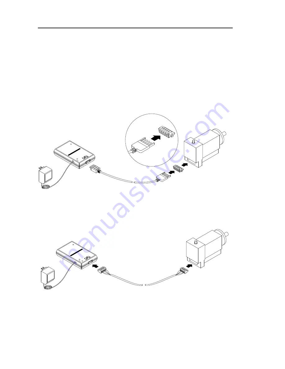
Connect to an unsealed device in one of two ways:

use a 1787-PCABL probe cable

Power

Supply

Generic

Unsealed

Device

20409a

1770KFD

Probe Cable

use DeviceNet drop or trunk cable

Power

Supply

Generic

Unsealed

Device

20409b

1770KFD

DeviceNet Drop or 

Trunk Cable

Summary of Contents for CDN366

Page 1: ...CDN366 DeviceNet Gateway Application Notes ...

Page 2: ...etting Using RSNetWorx 16 Serial Stream Object Parameters Class Code 64 17 Serial Receive Object Parameters Class Code 65 20 Serial Transmit Object Parameters Class Code 66 22 Serial Receive Transmit I O Mapping 25 Receive Handshaking I O Mapping 25 Transmit Handshaking I O Mapping 27 Mapping the Poll I O Connection to AB 1747 SDN 30 Basic Troubleshooting 35 ASCII Table 36 CDN366 Enclosure Dimensi...

Page 3: ...3 Revision Initial Release 6 12 01 ...

Page 4: ...k users to use the same configuration Based on application requirements the CDN366 can integrate with many brands of PLC AB Omron etc or PC based platforms Synergetic etc As long as a DeviceNet network is available for a particular application the CDN366 should be able to integrate in the network Hardware 1 AB SLC500 4 slot rack cat 1747 A4 series B 2 AB SLC500 power supply cat 1747 P1 series A 3 ...

Page 5: ... 8 points input module on slot 2 1746 IV8 and an 8 points output module on slot 3 1747 OB8 For further hardware and software configurations please visit Allen Bradley website at http www ab com The 24vdc regulated power supply is powered the network BUS 0vdc and BUS 24vdc on DIP790 board DIP790 is a DeviceNet distribution board with 1 inline 6 outline connections The DIP790 is connected to an AB 1...

Page 6: ...GND RTS CTS DeviceNet Connector black white to pin 1 DeviceNet connector black clear data high CAN H V BUS Terminal Connector BUS 0vdc Shield Drain white Description red V BUS data low CAN L shield Drain black blue clear CDN366 RS232 DeviceNet DeviceNet Gateway Module PC Interface Color to pin 5 DeviceNet connector 1770 KFD RS232 DeviceNet PC Interface Mod DIP790 Device Net Dist Board Slot 3 Power...

Page 7: ...adley PLC controller please visit www ab com In this particular example the hardware and software were setup and configured based upon page 1 listing The figures below demonstrate that the RSNLinx and RSNetWorx are running The DeviceNet scanner module scanned the network and found node 00 master DeviceNet scanner and node 03 slave interface module It is recommended to setup the DeviceNet master sc...

Page 8: ...aud rate Set the Mac ID to an unused node address The example below shows that the CDN366 was set at Mac ID 01 MSD 0 LSD 1 and DeviceNet network baud rate is at 125Kb RS 232 9 pin DIN male connector Connect to serial perhiphial Micro style male connector 5 pin to DeviceNet network Connect the CDN366 to the DeviceNet network and click on the network scan Online icon The DeviceNet master will scan t...

Page 9: ...9 In order to register the CDN366 on RSNetWorx click on Tools and select EDS Wizard Click on Next and the Options menu is prompted Select Register an EDS file s and click on Next ...

Page 10: ...10 Select Register a single file and enter the EDS file name on the white box Click on Next ...

Page 11: ...menu is prompted click on Next The Change Graphic Image menu is prompted Select CDN366 and click on Change icon Select another icon to replace current CDN366 icon Click OK to exit Change Icon menu After it is changed to a new icon click on Next ...

Page 12: ...n Finish to complete the EDS Wizard On RSLinx and RSNetWorx click on the Online icon to re scan or browse the network The CDN366 should be identified on the RSLinx and RSNetWorx network If after registering the EDS file the CDN366 is unrecognized on the DeviceNet network see the Troubleshooting Guide on page 35 ...

Page 13: ...ation Now the CDN366 is on the DeviceNet network To change the CDN366 parameters ensure that the CDN366 device is not on the DeviceNet master scanlist To edit the parameters on CDN366 point the mouse to CDN366 icon and right click ...

Page 14: ...en the sub menu is prompted click on Properties and the CDN366 menu appears Select Parameters and the EDS Editor sub menu is prompted Click on Upload and the default parameters will upload from CDN366 device ...

Page 15: ... Upload parameters from device Restore default parameters Monitor Parameters The CDN366 has eight 8 Rx Tx instances The total number of parameters are 155 On the Groups selection click on the down arrow key and then select Serial Stream Object Rx Inst 1 or Tx Inst 1 ...

Page 16: ...ter to accept the new value 2 Click on Apply and click on Yes to download new changes to CDN366 Another method for changing the parameters on CDN366 is using RSNetWorx 1 Point mouse to CDN366 icon and right click The sub menu is prompted 2 Click on Class Instance Editor and the WARNING alert menu is prompted 3 Click on Yes to access the class instance editor menu Service Code Used to verify or set...

Page 17: ...ications the stop bit is set at 1 The stop bits should be set to match the serial connection 1 Each data byte character transmit is followed by one zero 0 2 Each data byte character transmit is followed by two zeros 0 5 Flow Control The flow control can be set at 0 1 or 2 When flow control is set to 1 the X Off CTRL S will force the CDN366 s transmit function to block The transmitted characters ar...

Page 18: ...Attribute 11 01 02 Pos delimiter Class 64 Instance 1 Attribute 12 02 03 13 First byte is defined as bytes length in ASCII characters The 01 is equivalent to 1 byte length which is in Pre Delimiter The 02 is equivalent to 2 bytes length which is that set in Post Delimiter Timeout When Timeout Delimiter is enabled the value is set at Packet Timeout Class 64 Instance 1 Attribute 13 which will delay t...

Page 19: ... Instance 1 Bit 1 is set for receive toggling in Instance 2 and so on see Serial Receive Transmit I O Mapping section When Poll I O Connection is established with Allen Bradley 1747 SDN DeviceNet master scanner the produce size number of bytes will map into discrete Input data memory or M file table 9 Poll Consume Size This attribute can be accessed as read only When establishing a short string da...

Page 20: ...Use Post String bit 2 When this parameter bit is set to 1 the post string ASCII characters bytes will be removed before the PLC receives data from DeviceNet Post string characters are the serial ASCII characters found after the data 10 Receive Toggle This parameter is read only When new data has been received bit 0 is toggle see Receive Handshaking I O Mapping 11 Receive Acknowledge The value in t...

Page 21: ...e width class 65 instance 1 attribute 11 for a real or integer data type is 16 Example In order to receive a real value as 1 2345E 16 the width should be set to at least 11 When the width is set to 7 the received real value is 1 2345 16 Conversion The conversion class 65 instance 1 attribute 13 is valid only when the Data Type is an integer type The conversion can convert from hexadecimal X to dec...

Page 22: ...of eight transmit instances in CDN366 Note that Tx Ack Tx toggle Rx Ack and Rx Toggle are attributes used in the poll command and poll response to control the serial DeviceNet data transfer and do not need to be set explicitly as part of the CDN366 setup 20 Transmit Toggle The transmit toggle byte for 8 instances are mapped to 1747 SDN Output I O table Instance 1 transmit toggle is bit 0 Bit 0 one...

Page 23: ... Before Data String1 After String2 After String1 Before Data String2 After STX Data ETX CR 23 Data Type When 194 or 198 is entered for Data Type class 66 instance 1 attribute 9 one byte will be allocated for Data Size class 66 instance 1 attribute 10 When 195 or 199 is entered for Data Type two bytes will be allocated for Data Size When 202 is entered for Data Type four bytes will be allocated for...

Page 24: ...exadecimal When bit 0 is set to 0 the transmitted integer value will be converted to decimal Bit 7 is set to 1 to enable Leading Zeros When Leading Zero is enabled the zeros are padded in front of the data Decimal Hex Date Size byte Value Range 194 0xC2 1 128 127 195 0xC3 2 32768 32767 198 0xC6 1 0 255 199 0xC7 2 0 65535 202 0xCA 4 1 175E 38 3 4028E 38 218 0xDA Short_String Set by data size attrib...

Page 25: ... data memory table The serial data in the M file must be copied to a N integer file in order to be able to view the data Receive Handshaking I O Mapping The Receive Toggle byte for instances 1 8 is mapped in Input word I 1 1 word bits 8 15 Each receive toggle bit is controlled by a single instance of receive object When Instance 1 is used for serial reception bit 8 at Input I 1 1 would be used for...

Page 26: ...Instance 1 Receive Toggle and Receive Acknowledge When data is received on the RS232 serial the Receive Toggle bit 8 in input I 1 1 Rx instance 1 is toggled from 0 to 1 The first byte of the received data is the data size length which is stored in Input I 1 2 bits 0 7 The data is stored in Input I 1 2 bits 8 15 and so on see Input Memory Table of Allen Bradley 2 To acknowledge that data was receiv...

Page 27: ...e 1 Receive ASCII Character 1 Instance 1 Receive Data Size length I 1 2 I 1 1 Inst1 bit8 Inst2 bit9 Inst8 bit15 I 1 3 Instance 1 Receive ASCII Character 3 Instance 2 Receive ASCII Character 1 I 1 4 I 1 5 Instance 2 Receive ASCII Character 3 Input Memory Table of Allen Bradley 1747 SDN DeviceNet Master Scanner Module Data Memory Table 15 14 13 12 11 10 9 8 7 6 5 4 3 2 1 0 Transmit Tx Acknowledge bi...

Page 28: ...g for Transmit Toggle Output word O 1 1 bit 0 is 0 In order to send ASCII data out to the RS232 serial connection the Transmit Toggle bit 0 must toggle from 0 to 1 2 Specify the number of characters bytes to be transmitted This transmit data size must be entered in Output word O 1 2 bits 0 7 3 Enter the ASCII data in the Output memory table starting in Word O 1 1 bits 8 15 to be transferred to RS2...

Page 29: ...I O 1 byte 8 bits 1 byte 8 bits Reserved Read Only Transmit Tx Toggle bits 0 7 Inst1 bit0 Inst2 bit1 Inst8 bit7 Instance 1 Transmit ASCII Character 2 Instance 2 Transmit Data Size length Instance 2 Transmit ASCII Character 2 Data Memory Table 15 14 13 12 11 10 9 8 7 6 5 4 3 2 1 0 MO 0 149 MO 0 0 Instance 1 Transmit ASCII Character 1 Instance 1 Transmit Data Size length MO 0 1 O 1 1 Receive Rx Ackn...

Page 30: ...cket The data size for Short String data type for each serial receive transmit is Data Size bytes 1 number of ASCII character to receive The constant 1 is one byte reserve for the short string data size length So if 3 bytes of short string data are used the data size should be set to 4 bytes to include the length byte Example Using RSNetWorx for DeviceNet to map CDN366 for receiving 14 bytes of ba...

Page 31: ... 218 10 Click on Rx Inst 1 Data in Poll Command and set Data in Poll 11 Disable Rx Inst 2 to Rx Inst 8 serial receive by setting Data not in Poll 12 Click on Rx Inst 1 in Groups and select Tx Inst 1 13 Click on Tx Inst 1 Data Size and enter 2 14 Since this example uses the short string data type Click on Tx Inst 1 Data Type and enter 218 15 Click on Tx Inst 1 Data in Poll Command and set In Poll C...

Page 32: ...the new configuration The 17 and 4 bytes are needed to map to 1747 SDN module 20 In RSNetWorx right click on the CDN366 icon 21 Double click on Properties 22 The 1747 SDN Scanner Module menu is prompted 23 Click on Scanlist and Scanner Config Applet A menu is prompted 24 Click on Upload to upload parameters from scanner module ...

Page 33: ...The byte values from Poll Produce Size and Poll Consume Size are 17 and 4 28 Enter 17 on box Rx Size bytes 29 Enter 4 on box Tx Size bytes 30 Click on OK 31 User preference Do You want to Automap this data In this particular example click on Yes If No user must select to manually map I O in the memory tables ...

Page 34: ...nfigurations The memory Map To is Discrete not M file based on user preference applications The data map starts in the memory register of Word 1 Bit 0 The Output Bit Length is 32 equivalent to 4 bytes and the Input Bit Length is 136 equivalent 17 bytes Click on Close to exit Click on Apply Click Yes to download these changes to 1747 SDN memory ...

Page 35: ...e power to reset the NET LED address Verify node address is not occuppied by another device Verify node address is setup by software or hardware Verify DeviceNet network baud rate 2 Device minor and major revisions do not match EDS file Verify EDS file minor major revisions 4 Disconnect the device before changing the node rate Could be caused by 1 EDS file is not registered Problem 2 DeviceNet mas...

Page 36: ... line feed ctrl J 10 0A LF 42 2A 74 4A J 106 6A j vertical tab ctrl K 11 0B VT 43 2B 75 4B K 107 6B k form feed ctrl L 12 0C FF 44 2C 76 4C L 108 6C l carriage feed ctrl M 13 0D CR 45 2D 77 4D M 109 6D m shift out ctrl N 14 0E SO 46 2E 78 4E N 110 6E n shift in ctrl O 15 0F SI 47 2F 79 4F O 111 6F o data line escape ctrl P 16 10 DLE 48 30 0 80 50 P 112 70 p device control 1 ctrl Q 17 11 DC1 49 31 ...

Page 37: ... 26 1A SUB 58 3A 90 5A Z 122 7A z escape ctrl 27 1B ESC 59 3B 91 5B 123 7B file separator ctrl 28 1C FS 60 3C 92 5C 124 7C group separator ctrl 29 1D GS 61 3D 93 5D 125 7D record separator ctrl 30 1E RS 62 3E 94 5E 126 7E unit separator ctrl _ 31 1F US 63 3F 95 5F _ 127 7F DEL ...

Page 38: ...38 CDN366 Enclosure Dimensions 0 65 0 45 0 50 0 12 Mtg Holes 1 225 2 0 19 DIA 1 225 0 725 0 625 DIA On Case Wall 0 70 1 10 1 25 0 542 3 30 4 30 3 80 ...

Page 39: ...39 CDN366 Template Class Instance Attribute Default Setting Unit Comments ...

Page 40: ...try acronyms no need to know catalog numbers to view the wiring diagrams POWERFLEX 700 AC DRIVE PowerFlex 700 bookshelf design saves you volumes of space Convenient side by side mounting optimizes panel space and gives you unmatched configuration flexibility COMPACTLOGIX Part of the Logix family CompactLogix offers compact design expansive modularity and numerous communication capabilities for mac...

Page 41: ...Copyright 2002 Rockwell Automation All rights reserved Important Notices Allen Bradley Home Page http www ab com 2 of 2 2 19 2002 1 24 08 PM ...

Page 42: ... 2000 1747 PP008A EN P Firmware Release Note May 2001 1747 RN653A EN P RSNetWorx for ControlNet Compatibility with the SLC ControlNet Scanner Adapter 1747 ACN15 ACNR15 SCNR Release Note May 2000 CNET RN001A EN P SLC 500 Remote I O Adapter Module 1747 ASB Product Data Apr 1996 1747 2 38 Installation Instructions May 2001 1747 IN014B EN P User Manual Dec 1996 1747 6 13 Analog I O Modules Product Cat...

Page 43: ...imulator 1746 SIM Installation Instructions Oct 2001 1746 IN024A EN P Program Storage Device Installation Instructions 1747 PSD Installation Instructions Nov 2001 1747 IN001B EN P Chassis Power Supplies RTBs Product Title Catalog Number Publication Type Date Publication Number SLC Expansion Chassis Inaccurate I O Configuration Report for SLC 500 with RSLogix 500 Programming Software 1746 A2 Applic...

Page 44: ...47 2 33 Installation Instructions Feb 2000 1747 IN005A US P User Manual Jun 1996 1747 6 8 Distributed I O Scanner 1747 DSN Product Data May 1998 1747 2 35 DH 485 RS 232C Interface Module 1747 KE Installation Instructions Feb 2000 1747 IN006A US P DH 485 RS 232C Interface Module Firmware Upgrade 1747 KEU Installation Instructions March 1994 1747 5 4 ControlNet Messaging Module 1747 KFC15 Product Pr...

Page 45: ...l I O Modules Product Title Catalog Number Publication Type Date Publication Number Barrel Temperature Control Module 1746 BTM User Manual Apr 2001 1746 UM010B EN P Open Loop Velocity Control Module Addresses Common Hydraulic Problems 1746 QV Product Profile Feb 1997 1746 1 10 Programming Device Product Title Catalog Number Publication Type Date Publication Number SLC 500 and MicroLogix Program St...

Page 46: ...2 precautionary statements 2 handling the module 4 terminology 4 related publications 4 contents of your order 5 introduction to the RS 232 module 8 communicating on DeviceNet 9 mounting the module 10 supplying power 12 connecting cables via RS 232 to a computer 14 connecting cables via RS 232 to a modem 16 connecting cables via DeviceNet 17 installing the 1770 KFD driver 22 interpreting status in...

Page 47: ...adley does not assume responsibility or liability to include intellectual property liability for actual use based upon the examples shown in this publication Allen Bradley publication SGI 1 1 Safety Guidelines for the Application Installation and Maintenance of Solid State Control available from your local Allen Bradley office describes some important differences between solid state equipment and ...

Page 48: ...trial Environment EN 50082 2 EMC Generic Immunity Standard Part 2 Industrial Environment The product described in this manual is intended for use in an industrial environment Low Voltage Directive This apparatus is also designed to meet Council Directive 73 23 EEC Low Voltage by applying the safety requirements of EN 61131 2 Programmable Controllers Part 2 Equipment Requirements and Tests For spec...

Page 49: ...ion network designed to connect control systems to plant floor devices e g sensors push buttons motor starters and drives DeviceNet is based on commercially available technology and can be used by any company to develop interoperable products node configuration to configure the node address and data rate before a device is connected to a DeviceNet network parameter configuration to configure the o...

Page 50: ...one DeviceNet RS 232 interface module catalog no 1770 KFD one 1770 KFD driver diskette two DIN rail mounting brackets four DIN rail mounting bracket screws one 6 ft 9 pin D shell RS 232 null modem cable one unsealed DeviceNet terminal connector one copy of publication 1770 5 6 DeviceNet RS 232 Interface Module Installation Instructions If you ordered catalog no 1770 KFDG your order also includes a...

Page 51: ...9V ac power supply adapter 90 260V ac which comes with catalog no 1770KFDG A domestic 9V ac power supply adapter 120V ac which you can order separately as catalog no 1787USADPTR A Each adapter connects to the power supply connector on the 1770 KFD module See page 12 for additional information ...

Page 52: ...ABL which you can order separately T tap cable This cable connection lets the 1770 KFD module and a device connected to the module in a point to point configuration draw power from the network a 6 ft unsealed to sealed DeviceNet drop cable catalog no 1787 MCABL which you can order separately Unsealed drop cable Each cable connects to the 5 pin unsealed receptacle on the 1770 KFD module See cable c...

Page 53: ...unication interface that provides a host computer access to a DeviceNet network host computer 1770 KFD module RS 232 cable RS 232 serial port Figure 1 1770 KFD module 9 pin D shell RS 232 connector 5 pin unsealed connector power switch power supply connector Network Status indicator Module Status indicator RS 232 Status indicator 20294 wiring connection diagram Side 1 Side 2 ...

Page 54: ...omputer directly to device via the 1770 KFD module The host computer uses a point to point connection for node and or parameter configuration device host computer 1770 KFD module DeviceNet cable RS 232 cable power supply via a DeviceNet network connection host computer 1770 KFD module DeviceNet network RS 232 cable devices 1771 SDN scanner 1747 SDN scanner ...

Page 55: ...iagnostics Allen Bradley DeviceNet Manager software 1787 MGR manages data transmission and reception through the 1770 KFD interface module from a personal computer Windowst operating system Mounting the 1770 KFD Module You can mount the module on a DIN rail 1 Use the four screws to attach the two mounting brackets to the back of the module 20296 ...

Page 56: ...DeviceNet RS 232 Interface Module 11 Publication 1770 5 6 June 1996 2 Snap the mounting brackets onto the DIN rail 20297 ...

Page 57: ...r from a DeviceNet network Supplying Power via AC Wall Adapter Figure 2 shows the power supply catalog no 1787 USADPTR that takes 120V ac and outputs 9V dc at 1 amp Figure 2 Domestic 9V ac wall adapter 20299 Figure 3 shows the global power supply which takes 90 260V ac 47 63 Hz and outputs 9V dc This power supply is available only with the 1770 KFD module as catalog no 1770 KFDG ...

Page 58: ...ower via Network The DeviceNet network can power the 1770 KFD module Important When the module is connected to a powered DeviceNet network the network connection overrides the external power supply Supplying Power to a Device The module can supply power to a device in a point to point connection The device being powered in a point to point connection can draw a maximum of 100 mA at 12V dc 5 ...

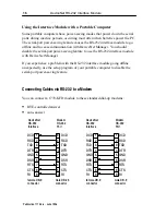
Page 59: ...7 RTS PIN 8 CTS PIN 9 RI Bottom of the 1770 KFD 20295a R S 2 3 2 Use these wiring configurations 5 2 3 4 6 1 7 8 9 GND RXD TXD DTR DSR DCD RTS CTS RI 7 2 3 6 8 20 4 5 22 female DB 9 connector female DB 9 connector DeviceNet RS 232 Interface Host RS 232 Port female DB 9 connector female DB 25 connector DeviceNet RS 232 Interface Host RS 232 Port GND TXD RXD DSR DCD DTR RTS CTS RI 5 2 3 4 6 1 7 8 9 ...

Page 60: ...CD data carrier detect in 2 RXD receive data in 3 TXD transmit data out 4 DTR data terminal ready out 5 GND signal ground 6 DSR data set ready in 7 RTS request to send out 8 CTS clear to send in 9 RI ring indicator in Connect the 1770 KFD module to a computer by using the RS 232 cable RS 232 cable to host computer 20295b retentive locking screws IMPORTANT If you build your own RS 232 cable it must...

Page 61: ...nager If you experience a problem with the RS 232 interface module going offline unexpectedly use the setup program of your portable computer to disable the serial port power saving feature Connecting Cables via RS 232 to a Modem You can connect a 1770 KFD module to these standard dial up modems DTE controlled answer auto answer DCD RXD TXD DTR GND DSR RTS CTS RI 1 2 3 4 5 6 7 8 9 8 3 2 20 7 6 4 5...

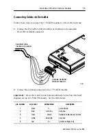
Page 62: ...cable trunkline or dropline unsealed DeviceNet terminal connector 20295c red white shield blue black 2 Connect the terminal connector to the 1770 KFD module Important DeviceNet cable connections should match color bars electrical diagram on top of 1770 KFD module See the table below pin number wire color abbreviation description 1 black V power return 2 blue data low data line 3 clear shield betwe...

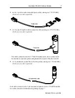
Page 63: ...onnect the module to a sealed or an unsealed device in a point to point configuration Connect to an unsealed device in one of two ways use a 1787 PCABL probe cable Power Supply Generic Unsealed Device 20409a 1770 KFD Probe Cable use DeviceNet drop or trunk cable Power Supply Generic Unsealed Device 20409b 1770 KFD DeviceNet Drop or Trunk Cable ...

Page 64: ...nect to a sealed device in one of three ways use a 1787 TCABL T tap cable and power supply Power Supply Generic Sealed Device 20409c 1770 KFD T tap Cable use a 1787 TCABL T tap cable and draw power from the network Generic Sealed Device 20409d 1770 KFD T tap Cable Network ...

Page 65: ...nd power supply Power Supply Generic Sealed Device 20410a Unsealed Drop Cable 1770 KFD T tap Probing a Network You can probe a sealed or an unsealed network with the 1770 KFD module Probe an unsealed network in one of two ways use a 1787 PCABL probe cable 1770 KFD Probe Cable Generic Unsealed Device 20766 M ...

Page 66: ...Interface Module 21 Publication 1770 5 6 June 1996 use a DeviceNet terminal connector 1770 KFD 20767 M Probe a sealed network in this way use a 1787 MCABL unsealed drop cable 20410e Unsealed Drop Cable 1770 KFD Network ...

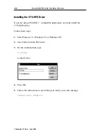
Page 67: ... WinDNett compatible application you must install the 1770 KFD driver Follow these steps 1 Start Windows 3 1 Windows 95 or Windows NT 2 Select Run from the File menu 3 On the command line type a setup as shown here 4 Press OK 5 Follow the instructions in each dialog box until you see the message Installation Complete ...

Page 68: ...and its connections Figure 4 identifies each status indicator Figure 4 Status indicator locations DeviceNET RS 232 Network Status Indicator Module Status Indicator RS 232 Status Indicator NETWORK STATUS MODULE STATUS RS 232 STATUS DC IN 9V 1770 KFD 20298 The tables on page 24 outline the indicator condition and the corresponding status and explain what each condition means to you ...

Page 69: ...ion status indicates off off line KFD DeviceNet is off line flashing green on line KFD DeviceNet is on line but not communicating solid red link failed critical device has detected an error that has rendered it incapable of communicating on the link for example detected a duplicate node address or network configuration error solid green on line communicating data being transmitted or received RS 2...

Page 70: ...munication port one 9 pin RS 232 D shell cabling RS 232 cable see cable diagrams power requirements ac wall 9V 1 amp DeviceNet connector 11 25V 700mA 300mA ambient temperature rating operational 0 to 50 C 32 to 122 F storage 40 C to 85 C 40 to 185 F ambient humidity rating 5 95 physical size 5 125 x 3 25 x 1 125 in 13 017 x 8 255 x 2 857 cm weight 5 5 oz 156 gm Agency Certification when product or...

Page 71: ...lephone support and 24 hour emergency hotline software and documentation updates technical subscription services Engineering and Field Services application engineering assistance integration and start up assistance field service maintenance support Technical Training lecture and lab courses self paced computer and video based training job aids and workstations training needs analysis Repair and Ex...

Page 72: ...DeviceNet RS 232 Interface Module 27 Publication 1770 5 6 June 1996 ...

Page 73: ...eland India Indonesia Ireland Israel Italy Jamaica Japan Jordan Korea Kuwait Lebanon Malaysia Mexico Netherlands New Zealand Norway Pakistan Peru Philippines Poland Portugal Puerto Rico Qatar Romania Russia CIS Saudi Arabia Singapore Slovakia Slovenia South Africa Republic Spain Sweden Switzerland Taiwan Thailand Turkey United Arab Emirates United Kingdom United States Uruguay Venezuela Yugoslavia...

Reviews: